Section 3 - OPERATING INSTRUCTIONS
3.3CUTTING HEIGHT ADJUSTMENT
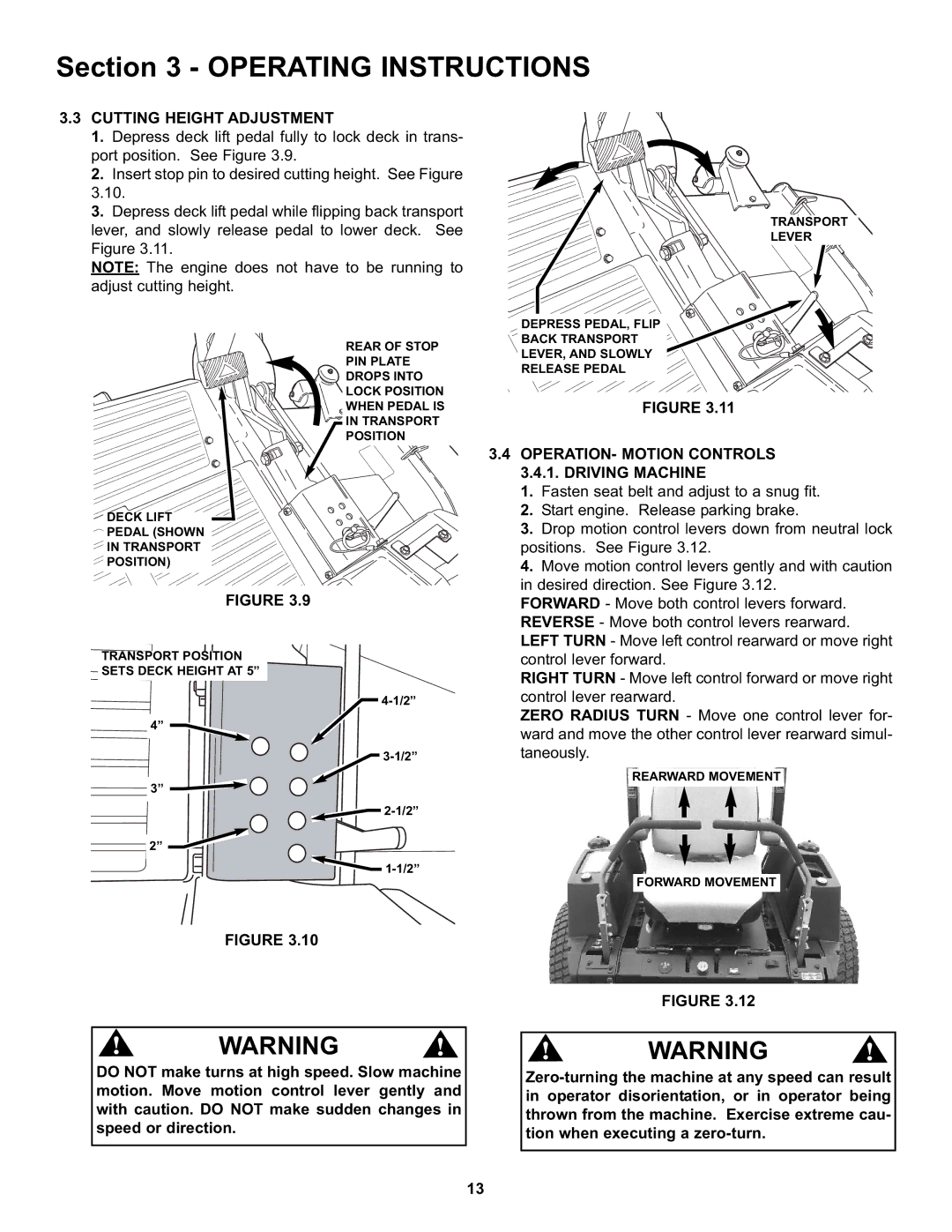
1.Depress deck lift pedal fully to lock deck in trans- port position. See Figure 3.9.
2.Insert stop pin to desired cutting height. See Figure
3.Depress deck lift pedal while flipping back transport lever, and slowly release pedal to lower deck. See Figure 3.11.
NOTE: The engine does not have to be running to adjust cutting height.
REAR OF STOP
PIN PLATE
DROPS INTO
LOCK POSITION
WHEN PEDAL IS
IN TRANSPORT
POSITION
DECK LIFT
PEDAL (SHOWN
IN TRANSPORT
POSITION)
FIGURE 3.9
TRANSPORT POSITION
SETS DECK HEIGHT AT 5”
4”
3”
2”
FIGURE 3.10
TRANSPORT
LEVER
DEPRESS PEDAL, FLIP
BACK TRANSPORT
LEVER, AND SLOWLY
RELEASE PEDAL
FIGURE 3.11
3.4OPERATION- MOTION CONTROLS 3.4.1. DRIVING MACHINE
1.Fasten seat belt and adjust to a snug fit.
2.Start engine. Release parking brake.
3.Drop motion control levers down from neutral lock positions. See Figure 3.12.
4.Move motion control levers gently and with caution in desired direction. See Figure 3.12.
FORWARD - Move both control levers forward. REVERSE - Move both control levers rearward. LEFT TURN - Move left control rearward or move right control lever forward.
RIGHT TURN - Move left control forward or move right control lever rearward.
ZERO RADIUS TURN - Move one control lever for- ward and move the other control lever rearward simul- taneously.
REARWARD MOVEMENT
FORWARD MOVEMENT
FIGURE 3.12
! | WARNING | ! |
DO NOT make turns at high speed. Slow machine motion. Move motion control lever gently and with caution. DO NOT make sudden changes in speed or direction.
! | WARNING | ! |
13