Manuals
/
Snapper
/
Lawn and Garden
/
Lawn Mower
Snapper
S211, SP211, SPV211, SPV211S, SPV211E
important safety instructions
Primary Maintenance
Models:
S211, SP211, SPV211, SPV211S, SPV211E
1
22
28
28
Download
28 pages
31.34 Kb
19
20
21
22
23
24
25
26
Troubleshooting
Warranty
Maintenance
Battery Service
Storage Procedure
Handle Height Adjustment
Safety
Belt Service
Page 22
Image 22
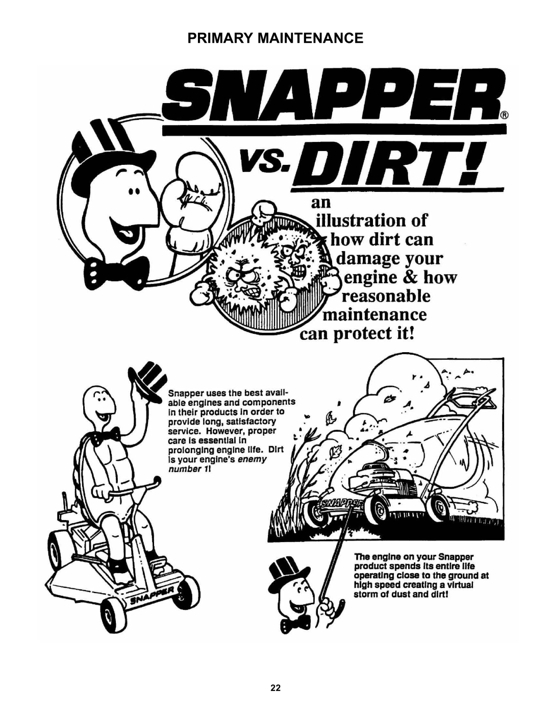
PRIMARY MAINTENANCE
22
Page 21
Page 23
Page 22
Image 22
Page 21
Page 23
Contents
21 ‘EASY LINE’ Walk Behind Mowers
Important Safety Instructions
Operation
From Previous
Important Safety Instructions
Table of Contents
Model SPV211 Shown Introduction
Familiarization
Nomenclature
PRE-START Check List
Operating Instructions
Starting & Operation Engine & Blade
Self Propelled Models Only
Handle Height Adjustment
Starting & Operation Propelling Mower
Stopping
Recycling Operation
Cutting Height Adjustment
To Remove Recycling Cover
Installation of Side Discharge Deflector
10INSTALLATION of Grass BAG Door Type Bag
Service Periodic
Maintenance
Service After First 5 Hours 3.2.1. Change Engine OIL
Check Mower Blade
Storage Procedure
Mower Blade Replacement 4.1.1. Standard Blade Wear Limit
Repair & Adjustments
Blade Sharpening
Wheel Drive Control Adjustment
Top of transmission pulley removed for clarity
To decrease minimum ground speed
To adjust idler spring tension
To increase minimum ground speed
Belt Service
Engine Drive Belt Replacement 1. Empty fuel tank
Battery Testing
Battery Service
Battery Storage
Battery Charging
Rear Cover Removal & Installation
Troubleshooting
Problem Probable Cause Corrective Action
100
SERVICEection3 SCHEDULE- OP Rating Instructions
Service Each
Performed USE HRS Season
Year Limited Warranty
Disclaimer of Warranty
Primary Maintenance
Primary Maintenance
Primary Maintenance
Primary Maintenance
Snapper Product Registration Form
Page
21 ‘EASY LINE’ Walk Behind Mowers
Top
Page
Image
Contents