Section 4 - REPAIR & ADJUSTMENTS
! | WARNING | ! |
DO NOT attempt any maintenance, adjustments or service with engine and blade running. STOP engine and blade. Disconnect spark plug wire and secure away from spark plug. Engine and components are HOT. Avoid serious burns, allow sufficient time for all components to cool.
4.2WHEEL DRIVE CONTROL ADJUSTMENT
The wheel drive control lever should engage the trans- mission when the lever is squeezed back against the handlebar, and disengage the transmission when the lever is released. See Figure 4.4.
| GROUND SPEED | WHEEL DRIVE |
| ||
| CONTROL | CONTROL |
| ||
| FAST |
|
|
|
|
|
|
|
| ||
|
|
| DISENGAGE | ||
|
|
|
|
|
|
SLOWENGAGE
FIGURE 4.4
If the transmission does not fully engage or disengage, adjustment may be performed as follows:
1.Remove rear cover from mower. Refer to Section “Rear Cover Removal & Installation”.
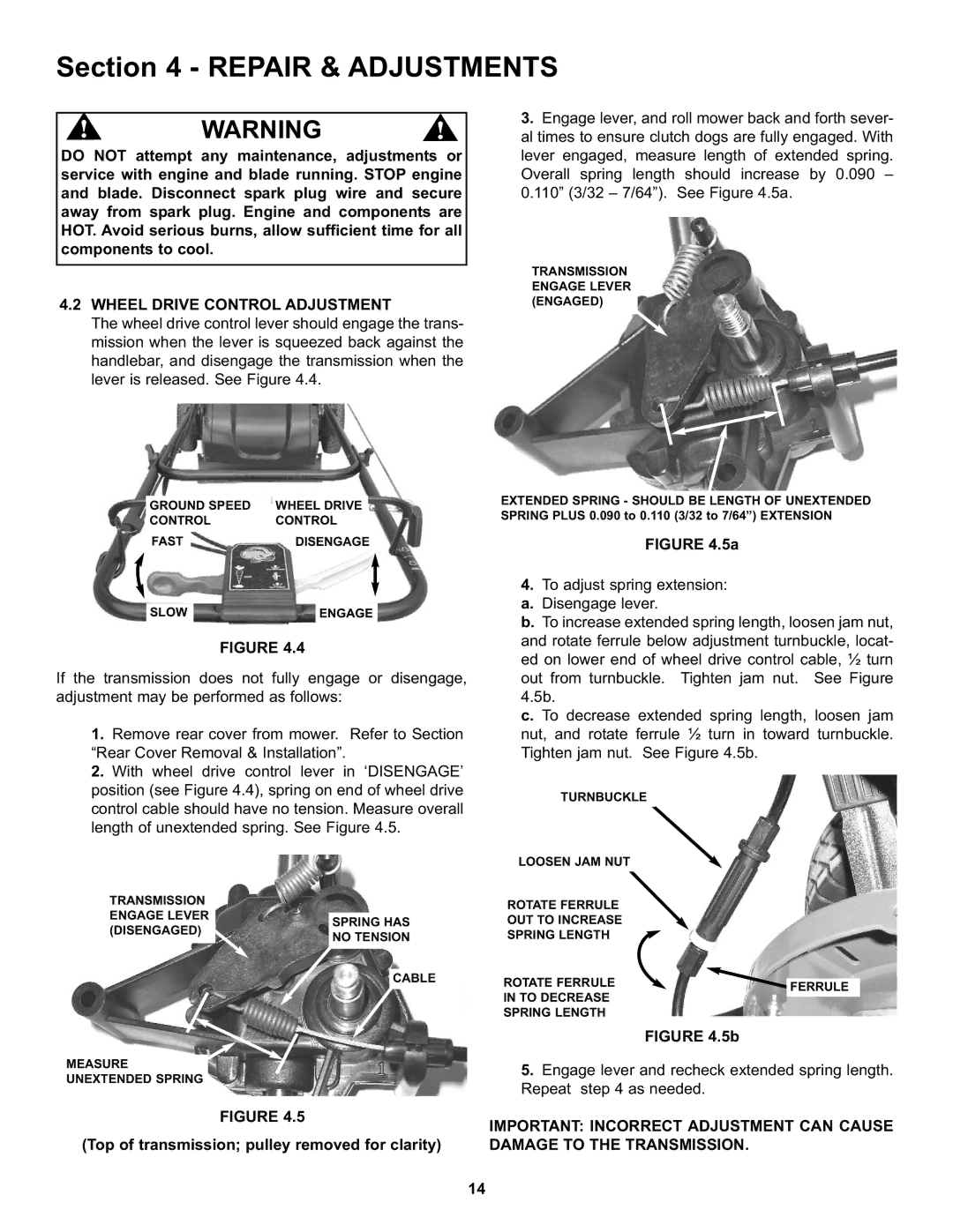
2.With wheel drive control lever in ‘DISENGAGE’ position (see Figure 4.4), spring on end of wheel drive control cable should have no tension. Measure overall length of unextended spring. See Figure 4.5.
TRANSMISSION
ENGAGE LEVER
3.Engage lever, and roll mower back and forth sever- al times to ensure clutch dogs are fully engaged. With lever engaged, measure length of extended spring. Overall spring length should increase by 0.090 – 0.110” (3/32 – 7/64”). See Figure 4.5a.
TRANSMISSION ENGAGE LEVER (ENGAGED)
EXTENDED SPRING - SHOULD BE LENGTH OF UNEXTENDED SPRING PLUS 0.090 to 0.110 (3/32 to 7/64”) EXTENSION
FIGURE 4.5a
4.To adjust spring extension: a. Disengage lever.
b. To increase extended spring length, loosen jam nut, and rotate ferrule below adjustment turnbuckle, locat- ed on lower end of wheel drive control cable, ½ turn out from turnbuckle. Tighten jam nut. See Figure 4.5b.
c. To decrease extended spring length, loosen jam nut, and rotate ferrule ½ turn in toward turnbuckle. Tighten jam nut. See Figure 4.5b.
TURNBUCKLE
LOOSEN JAM NUT
ROTATE FERRULE
(DISENGAGED)
SPRING HAS NO TENSION
CABLE
OUT TO INCREASE
SPRING LENGTH
ROTATE FERRULE |
|
|
| FERRULE | |
IN TO DECREASE |
| |
|
| |
|
| |
SPRING LENGTH |
|
|
|
|
|
FIGURE 4.5b
MEASURE
UNEXTENDED SPRING
FIGURE 4.5
(Top of transmission; pulley removed for clarity)
5.Engage lever and recheck extended spring length. Repeat step 4 as needed.
IMPORTANT: INCORRECT ADJUSTMENT CAN CAUSE DAMAGE TO THE TRANSMISSION.
14