Section 4 - REPAIR & ADJUSTMENTS
! | WARNING | ! |
DO NOT attempt any maintenance, adjustments or service with engine and blade running. STOP engine and blade. Disconnect spark plug wire and secure away from spark plug. Engine and components are HOT. Avoid serious burns, allow sufficient time for all components to cool.
4.4BELT SERVICE
On
4.4.1.Engine Drive Belt Replacement 1. Empty fuel tank.
2.Remove blade. Refer to Section “Blade Sharpening”.
3.Remove rear cover of mower. Refer to Section “Rear Cover Removal & Installation”.
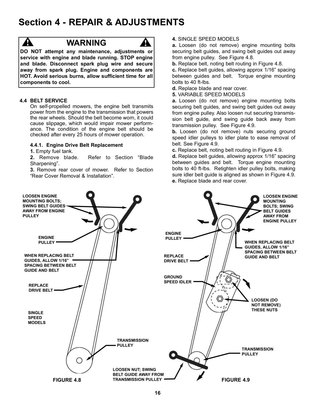
4.SINGLE SPEED MODELS
a. Loosen (do not remove) engine mounting bolts securing belt guides, and swing belt guides out away from engine pulley. See Figure 4.8.
b. Replace belt, noting belt routing in Figure 4.8.
c. Replace belt guides, allowing approx 1/16” spacing between guides and belt. Torque engine mounting bolts to 40
d. Replace blade and rear cover.
5.VARIABLE SPEED MODELS
a. Loosen (do not remove) engine mounting bolts securing belt guides, and swing belt guides out away from engine pulley. Also loosen nut securing transmis- sion belt guide, and swing guide back away from transmission pulley. See Figure 4.9.
b. Loosen (do not remove) nuts securing ground speed idler pulleys to idler plate to ease removal of belt. See Figure 4.9.
c. Replace belt, noting belt routing in Figure 4.9.
d. Replace belt guides, allowing approx 1/16” spacing between guides and belt. Torque engine mounting bolts to 40
LOOSEN ENGINE
MOUNTING BOLTS;
SWING BELT GUIDES
AWAY FROM ENGINE
PULLEY
ENGINE
PULLEY
WHEN REPLACING BELT GUIDES, ALLOW 1/16”
SPACING BETWEEN BELT GUIDE AND BELT
REPLACE
DRIVE BELT
SINGLE
SPEED
MODELS
FIGURE 4.8
ENGINE
PULLEY
REPLACE
DRIVE BELT
GROUND
SPEED IDLER![]()
TRANSMISSION
PULLEY
LOOSEN NUT; SWING
BELT GUIDE AWAY FROM
TRANSMISSION PULLEY
LOOSEN ENGINE
MOUNTING
BOLTS; SWING
BELT GUIDES
AWAY FROM
ENGINE PULLEY
WHEN REPLACING BELT
GUIDES, ALLOW 1/16”
SPACING BETWEEN BELT
GUIDE AND BELT
LOOSEN (DO
NOT REMOVE)
THESE NUTS
TRANSMISSION
PULLEY
FIGURE 4.9
16