XLogic E Signature™ Channel Owner’s Manual
4.3Dynamics Section
The Dynamics section of the XLogic E Signature Channel unit comprises a compressor/limiter and an expander/gate, both of which use the same gain change element. The design returns faithfully to the circuit and key components which defined the sound of the original E Series channel strip. A true RMS converter is used in the side chain whilst the gain element is an all discrete design identical to the Class A VCA chip used in the original unit. The compressor contains additional switching options to defeat the
As in the original E Series channel strip, the Filter and/or the Equaliser section can be assigned to the dynamics side chain allowing
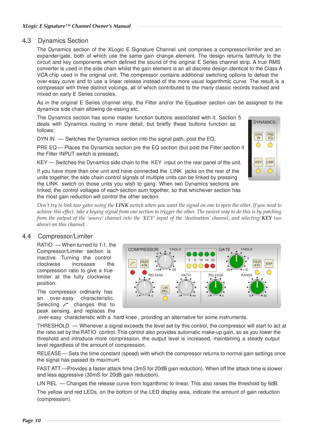
The Dynamics section has some master function buttons associated with it. Section 5 deals with Dynamics routing in more detail, but briefly these buttons function as follows:
DYN IN – Switches the Dynamics section into the signal path, post the EQ.
PRE EQ – Places the Dynamics section pre the EQ section (but post the Filter section if the Filter INPUT switch is pressed).
KEY – Switches the Dynamics side chain to the ‘KEY’ input on the rear panel of the unit.
If you have more than one unit and have connected the ‘LINK’ jacks on the rear of the units together, the side chain control signals of multiple units can be linked by pressing the LINK switch on those units you wish to gang. When two Dynamics sections are linked, the control voltages of each section sum together, so that whichever section has the most gain reduction will control the other section.
DYNAMICS ![]()
DYN PRE
IN EQ
KEY LINK
Don’t try to link two gates using the LINK switch when you want the signal on one to open the other. If you need to achieve this effect, take a keying signal from one section to trigger the other. The easiest way to do this is by patching from the output of the ‘source’ channel into the ‘KEY’ input of the ‘destination’ channel, and selecting KEY (see above) on this channel.
4.4Compressor/Limiter
RATIO – When turned to 1:1, the Compressor/Limiter section is inactive. Turning the control
clockwise increases the compression ratio to give a true limiter at the fully clockwise position.
COMPRESSOR | T/HOLD |
|
|
| GATE | T/HOLD |
| |
0 |
|
|
|
|
|
|
| |
| 3 | 6 | 10 | 14 | 20 | 0 |
| |
FAST | FAST | EXP | ||||||
|
|
|
|
| ||||
ATK |
|
|
|
|
| ATK | ||
|
|
|
|
|
| |||
+10 |
|
|
| +10 |
| |||
RELEASE | RATIO |
|
| RELEASE | RANGE |
| ||
LIN |
The compressor ordinarily has |
|
| REL |
|
|
|
| |
|
|
|
|
|
|
|
| |
an | .1 | 4 | 1 | .1 | 4 | 0 | 40 | |
|
|
|
|
|
|
| ||
Selecting | changes this to |
|
|
|
|
|
|
|
peak sensing, and replaces the |
|
|
|
|
|
|
| |
|
| |||||||
THRESHOLD – Whenever a signal exceeds the level set by this control, the compressor will start to act at the ratio set by the RATIO control. This control also provides automatic
RELEASE – Sets the time constant (speed) with which the compressor returns to normal gain settings once the signal has passed its maximum.
FAST ATT – Provides a faster attack time (3mS for 20dB gain reduction). When off the attack time is slower and less aggressive (30mS for 20dB gain reduction).
LIN REL – Changes the release curve from logarithmic to linear. This also raises the threshold by 6dB.
The yellow and red LEDs, on the bottom of the LED display area, indicate the amount of gain reduction (compression).
Page 10