Installation and Operation
5.0 Signal Routing
Channel Processing Order
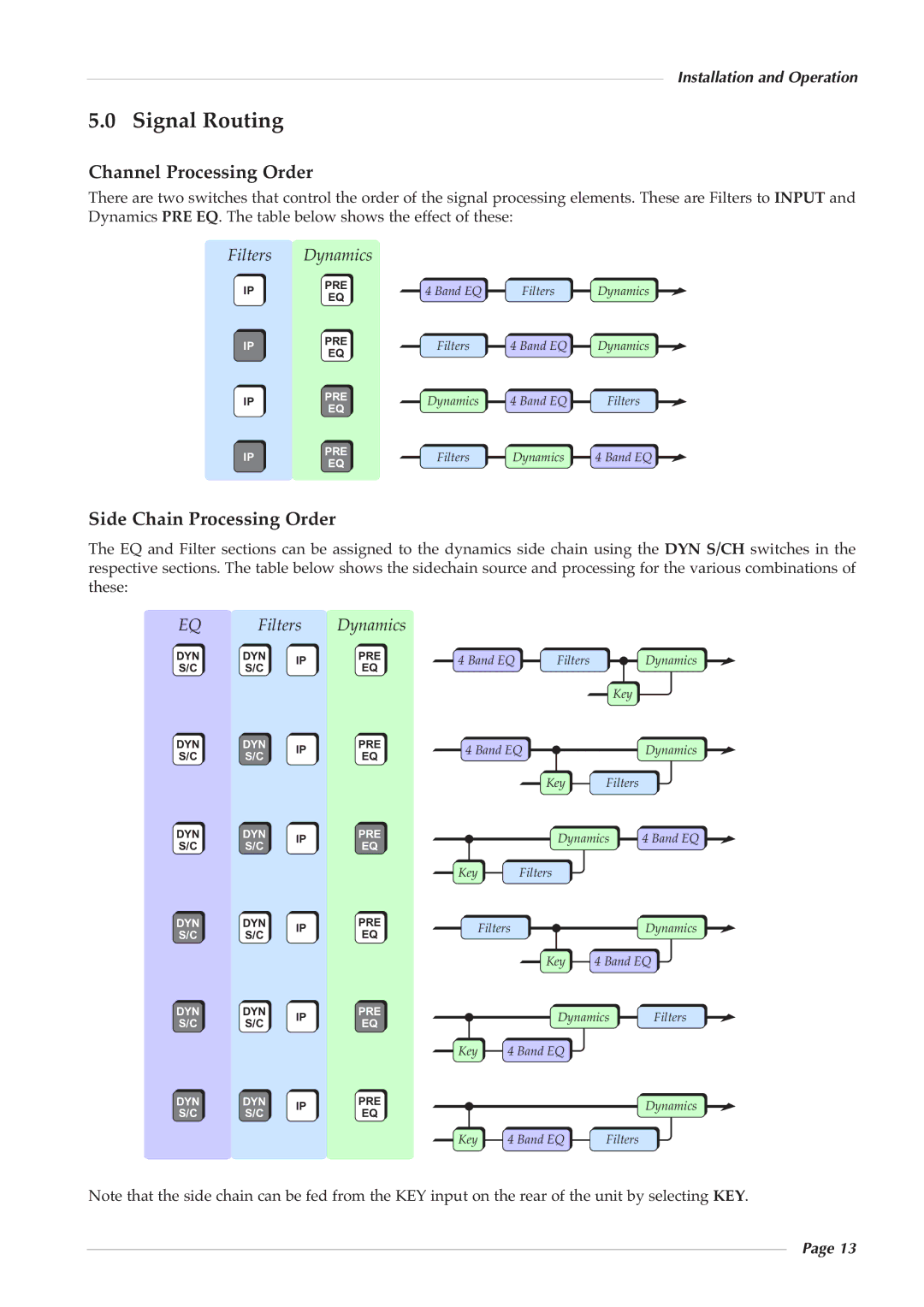
There are two switches that control the order of the signal processing elements. These are Filters to INPUT and Dynamics PRE EQ. The table below shows the effect of these:
Filters | Dynamics |
|
|
| |
IP | PRE | 4 Band EQ | Filters | Dynamics | |
EQ | |||||
|
|
|
| ||
IP | PRE | Filters | 4 Band EQ | Dynamics | |
EQ | |||||
|
|
|
| ||
IP | PRE | Dynamics | 4 Band EQ | Filters | |
EQ | |||||
|
|
|
| ||
IP | PRE | Filters | Dynamics | 4 Band EQ | |
EQ | |||||
|
|
|
|
Side Chain Processing Order
The EQ and Filter sections can be assigned to the dynamics side chain using the DYN S/CH switches in the respective sections. The table below shows the sidechain source and processing for the various combinations of these:
EQ | Filters | Dynamics |
|
|
|
|
| |
DYN | DYN | IP | PRE | 4 Band EQ | Filters |
| Dynamics | |
S/C | S/C | EQ |
| |||||
|
|
|
|
|
| |||
|
|
|
|
|
|
| Key |
|
DYN | DYN | IP | PRE | 4 Band EQ |
| Dynamics | ||
S/C | S/C | EQ |
| |||||
|
|
|
|
|
| |||
|
|
|
|
|
| Key | Filters |
|
DYN | DYN | IP | PRE |
|
| Dynamics | 4 Band EQ | |
S/C | S/C | EQ |
|
| ||||
|
|
|
|
|
| |||
|
|
|
| Key |
| Filters |
|
|
DYN | DYN | IP | PRE |
| Filters |
|
| Dynamics |
S/C | S/C | EQ |
|
|
| |||
|
|
|
|
|
| |||
|
|
|
|
|
| Key | 4 Band EQ | |
DYN | DYN | IP | PRE |
|
| Dynamics | Filters | |
S/C | S/C | EQ |
|
| ||||
|
|
|
|
|
| |||
|
|
|
| Key | 4 Band EQ |
|
| |
DYN | DYN | IP | PRE |
|
|
|
| Dynamics |
S/C | S/C | EQ |
|
|
|
| ||
|
|
|
|
|
| |||
|
|
|
| Key | 4 Band EQ | Filters |
| |
Note that the side chain can be fed from the KEY input on the rear of the unit by selecting KEY.
Page 13
