XLogic E Signature™ Channel Owner’s Manual
4.7Equaliser Section
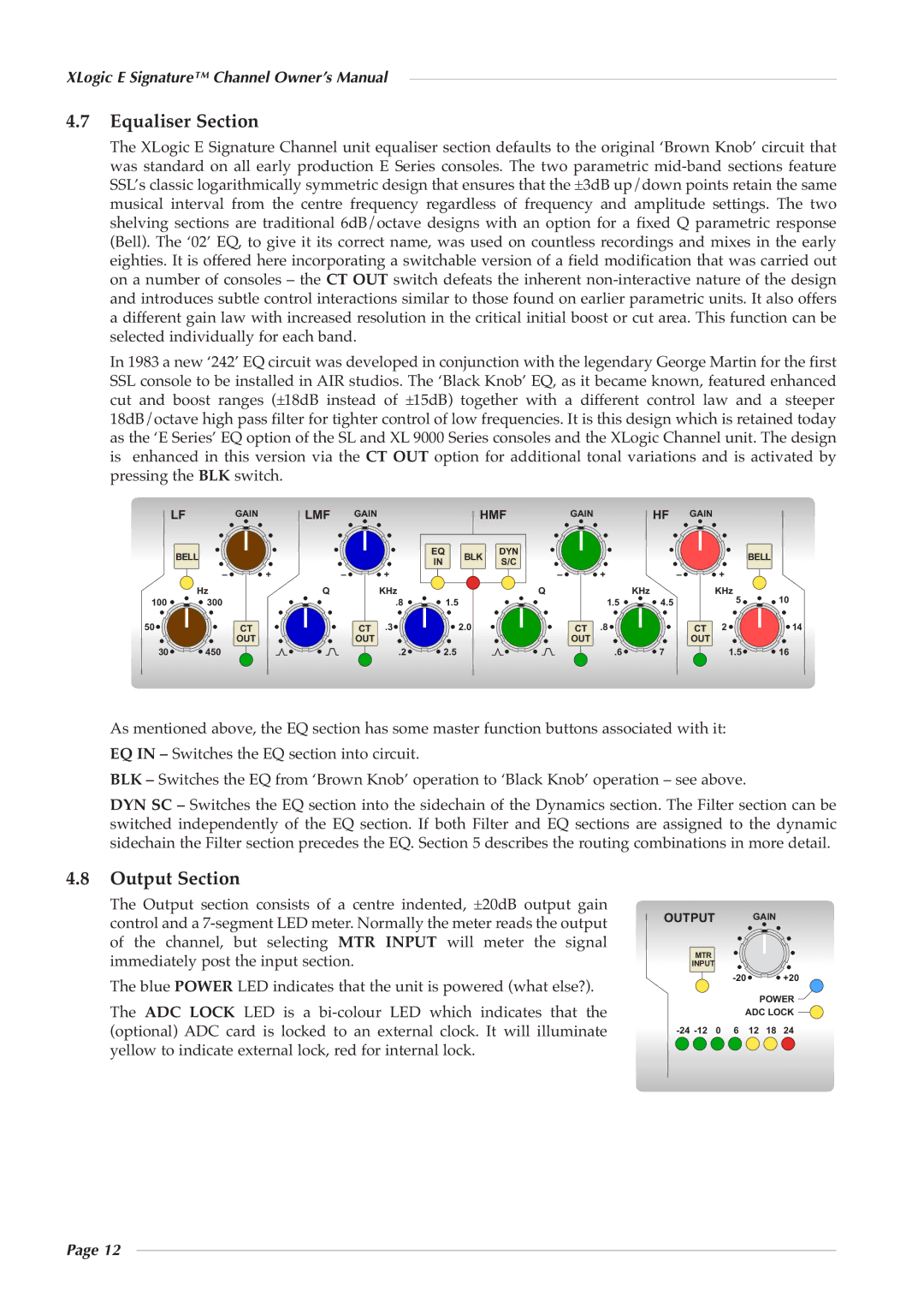
The XLogic E Signature Channel unit equaliser section defaults to the original ‘Brown Knob’ circuit that was standard on all early production E Series consoles. The two parametric
In 1983 a new ‘242’ EQ circuit was developed in conjunction with the legendary George Martin for the first SSL console to be installed in AIR studios. The ‘Black Knob’ EQ, as it became known, featured enhanced cut and boost ranges (±18dB instead of ±15dB) together with a different control law and a steeper 18dB/octave high pass filter for tighter control of low frequencies. It is this design which is retained today as the ‘E Series’ EQ option of the SL and XL 9000 Series consoles and the XLogic Channel unit. The design is enhanced in this version via the CT OUT option for additional tonal variations and is activated by pressing the BLK switch.
LF |
| GAIN | LMF | GAIN |
|
| HMF | GAIN |
| HF | GAIN |
|
| |
BELL |
|
|
|
| EQ | BLK | DYN |
|
|
|
|
| BELL | |
|
|
|
| IN | S/C |
|
|
|
|
| ||||
|
|
|
|
|
|
|
|
|
|
|
|
| ||
| – | + | – |
| + |
|
| – |
| + | – |
| + |
|
| Hz |
| Q |
| KHz |
|
| Q |
|
| KHz |
| KHz |
|
100 | 300 |
|
|
| .8 | 1.5 |
|
|
| 1.5 | 4.5 |
| 5 | 10 |
50 |
| CT |
| CT | .3 |
| 2.0 |
| CT | .8 |
| CT | 2 | 14 |
|
| OUT |
| OUT |
|
|
|
| OUT |
|
| OUT |
|
|
30 | 450 |
|
|
| .2 | 2.5 |
|
|
| .6 | 7 |
| 1.5 | 16 |
As mentioned above, the EQ section has some master function buttons associated with it:
EQ IN – Switches the EQ section into circuit.
BLK – Switches the EQ from ‘Brown Knob’ operation to ‘Black Knob’ operation – see above.
DYN SC – Switches the EQ section into the sidechain of the Dynamics section. The Filter section can be switched independently of the EQ section. If both Filter and EQ sections are assigned to the dynamic sidechain the Filter section precedes the EQ. Section 5 describes the routing combinations in more detail.
4.8Output Section
The Output section consists of a centre indented, ±20dB output gain control and a
The blue POWER LED indicates that the unit is powered (what else?).
The ADC LOCK LED is a
OUTPUT GAIN
MTR |
INPUT |
![]()
![]()
![]()
![]() +20
+20
POWER ![]()
ADC LOCK ![]()
Page 12