Projection TV
Specifications
Video Video in 2 Video 2 Input
Safety Relatedp Adjustments
Table of Contents
Disassembly
Diagrams
Welcome!Precautions
Installing the projection TV
Hookup
Connecting an antenna
To a conventional VCR
To a projection TV
Connecting a DBS receiver
To an S video equipped VCR
To a projection TV and VCR
Connecting an audio system
Connecting a camcorder
Connecting two VCRs for tape editing using Monitor OUT
Inserting batteries
Connecting a Sony Sava series speaker system
Getting to know buttons on the remote control
Button color
Setting up the projection TV automatically
Erasing or adding channels
Press Vor vto select Channel ERASE/ADD
Adjusting convergence
Setting cable TV on or off
Erase and/or add channels
Watching the TV
Presetting channels
Switching quickly between two channels
Muting the sound
Watching two programs at one time PIP
Changing the position of the window picture
Adjusting the picture Video
Freezing the picture
Swapping the main and window pictures
Adjusting
Press Vor vto select Ntsc STD, MEDIUM, or High and press
Using the menu to set audio effect
Using audio effect
Selecting Stereo or Setting the speaker Bilingual Programs
Using the audio effect button
Setting audio out
Setting daylight Setting the clock Saving time Daylight
Setting the timer to turn the projection TV on and off
Customizing the channel names
Setting your favorite channels
Blocking out a Setting Your
Setting video labels
Favorite Channels
Setting the manufacturer’s code
Setting Caption
Operating video equipment
Operating a cable box or DBS receiver
Operating video equipment
Index to parts and controls
Troubleshooting
Projection TV Front
Remote control
Rear Board Removal
Service Position
Chassis Assy Removal
HA Board Removal KP-41T65C
HA Board Removal KP-53S65C/61S65C
Beznet Assy Removal KP-53S65C
Beznet Assy Removal KP-41T65C
Screen Frame Assy Removal KP-61S65C
Mirror Cover Assy Removal KP-53S65C
Mirror Cover Assy Removal KP-41T65C
Reflection Mirror Removal KP-61S65C
Picture Tube Removal KP-41T65C
HIGH-VOLTAGE Cable Installation and Removal
Picture Tube Removal KP-53S65C/61S65C
Picture Tube Bracket Assy Removal KP-41T65C
Picture Tube Bracket Assy Removal KP-53S65C/61S65C
Setting of Service Stay ASSY. KP-41T65C/53S65C
Install a Chassis Assy
Focus Lens Adjustment
Screen Voltage Adjustment Rough Alignment
Screen G2 Adjustment
Focus VR Adjustment
Pole Magnet Adjustment
Deflection Yoke Tilt Adjustment
Defocus Adjustment Blue
Electrical Adjustment by Remote Commander
Display
Adjust Buttons and Indicator
Muting
GH Cent
BH 4PIN
Mscn Main SUB Contrast
Convergence Adjustment
GH Cent GH BOW GH Skew GH 4BOW
Green Vertical Size Adjustment
GV Wave
GV 4PIN
AGC Adjustment
White Balance Adjustment
HV HOLD-DOWN Adjustment
Board HV Regulation Circuit Check and Adjustment
HV Hold Down Circuit Operation Check and Adjustment
Operation Check
+B OVP Confirmation
SUB Contrast Adjustment Scon
BER Display Adjustment Disp
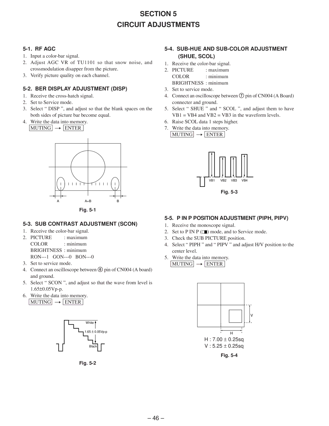
SUB-HUE and SUB-COLOR Adjustment SHUE, Scol
P Position Adjustment PIPH, Pipv
P SUB Contrast Adjustment Pcon
P SUB HUE, SUB Color Adjustment IHUE, Icol
Memo
Section Diagrams
Block Diagram
Comb FILTER,PIP Processor
Printed Wiring Boards and Schematic Diagrams
Frame Schematic Diagram
Circuit Boards Location
Board Waveforms
13Vp-p 500kHz 8Vp-p H 0Vp-p H 60Vp-p
Board
Diode
Board IC801, 802 PA0053B
8Vp-p H 7Vp-p H
4Vp-p H 2Vp-p H
5Vp-p 4Vp-p
2Vp-p H 8Vp-p 6Vp-p H
PT Board IC5052 SDA9288X-GEG PT Board Waveforms
PT Board IC Voltage List
PT Board
PT Board
CG Board Waveform
CR Board Waveform
140Vp-p H 160Vp-p H
CG Board IC701 TDA6106Q
CB Board Waveform
CR Board IC701 TDA6106Q
CB Board IC701 TDA6106Q
ZDY/VM
Board HA Board
STBY5V
Semiconductors
Cover KP-41T65C
66 68 5358
Cover KP-61S65C
+BVTP 3X12
170
Chassis KP-41T65C
217 201
Chassis KP-53S65C/61S65C
263
Picture Tube KP-41T65C
Picture Tube KP-53S65C/61S65C
KP-61S65C
Section Electrical Parts List
CONNECTOR, Board to Board 20P
REF. no Description
PT a
101
102
103
104
105
106
107
108
109
110
111
Relay
CR CG CB
CB HA
115
Accessories and Packing Materials MANUAL, Instruction
965-216-01