MDM-5A
Specifications
MDS-JE520
MBU-5A
SELF-DIAGNOSIS Function
Items of Error History Mode Items and Contents
Specification Label
Flexible Circuit Board Repairing
Parts No
Diagrams
Table of Contents
Disassembly
Exploded Views
Section Servicing Note
JIG for Checking BD Board Waveform
Record Precedure
Checks Prior to Parts Replacement and Adjustments
Criteria for Determination Measure if unsatisfactory
Forced Reset
Main Board Component Side
Cleaning of Objective Lens of Optical Pickup
Fluorescent Indicator Tube and Mechanism Deck
Attaching the Glass Assembly
Fluorescent Indicator TUBE, LED Complete Lighting Check
Servicing Position
Cause of Retry Occurring conditions
Retry Cause Display Mode
Higher Bits Lower Bits Hexa
Binary
Higher Bits Lower Bits Hexa Details
Bit When Binary
Hexadecimal Binary
Section General
Front Panel Location of Parts and Controls
Glass Assy
Section Disassembly
Front Panel
Slider CAM
Base Unit and BD Board
SW Board and Loading Motor M103
Setting the Test Mode
Section Test Mode
Precautions for USE of Test Mode
Exiting the Test Mode
Selecting the Test Mode
Group
Non-Volatile Memory Mode EEP Mode
Operating the Continuous Playback Mode
Functions of Other Buttons
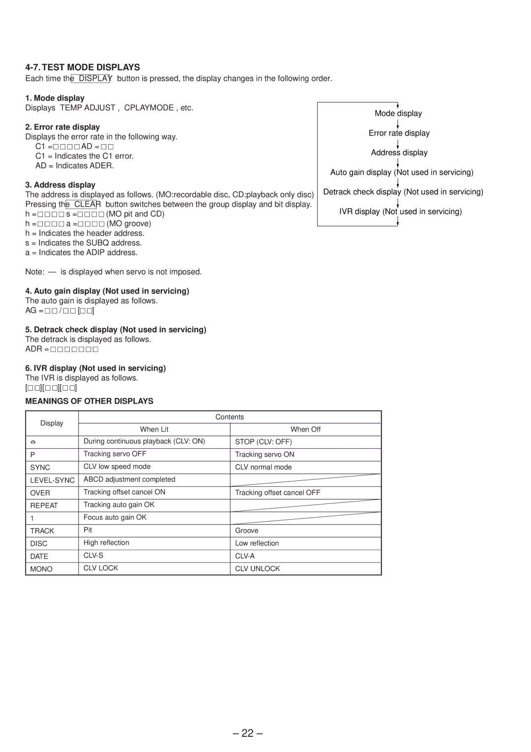
Test Mode Displays
Section Electrical Adjustments
Parts Replacement and Adjustment
Precautions for Adjustments
Precautions for Checking Laser Diode Emissinon
Precautions for USE of Optical PICK- UP KMS-260A
Creating Continuously Recorded Disc
Checks Prior to Repairs
Temperature Compensation Offset Check
Laser Power Check
Specified Value
Focus Bias Check
Play Checking MO Error Rate Check
CD Error Rate Check
Self-Recording/playback Check
Laser Power Adjustment
Initial Setting of Adjustment Value
Temperature Compensation Offset Adjutment
Recording and Displaying the IOP Information
Traverse Adjustment
Focus Bias Adjustment
CD Auto Gain Control Output Level Adjustment
Error Rate Check
Auto Gain Control Output Level Adjustment
MO Auto Gain Control Output Level Adjustment
Adjusting Points and Connecting Points
Section Diagrams
Circuit Boards Location
PB Digital out
Block Diagrams BD Section
MDS-SD1
REC Digital
PBDigital out
Main Section
RECDigital
Waveforms
For schematic diagrams
For printed wiring boards
Display Section
Printed Wiring Board BD Section
Semiconductor Location
Schematic Diagram BD 1/2 Section
Schematic Diagram BD 2/2 Section
Schematic Diagram Main 1/2 Section
Schematic Diagram Main 2/2 Section
Printed Wiring Board Main Section
Schematic Diagram Panel Section
Printed Wiring Board Panel Section
Schematic Diagram Connector Section
Printed Wiring Board Connector Section
System Control To HCD-SD1
MDS-SD1
IC Block Diagrams
BD Section IC101
Main Section IC201 UDA1341TS/N2
IC152 BH6511FS-E2
IC301 LB1641
IC822 M62016FP-E1
Connector Section IC774 P82B715TD.118
IC851 M5293L
IC101 CXA2523AR RF Amplifier BD Board
IC PIN Functions
Pin No Pin Name Function
IC701 M30610MC-A01FP System Control ∝CON Main Board
CHAK-IN
Section Exploded Views
Case and Back Panel Section
Panel SW Board
FL901 1-517-804-11 Indicator TUBE, Fluorescent
Front Panel Section
67 A-4724-619-A Panel BOARD, Complete
Insulator F
Mechanism Deck Section MDM-5A
209 4-988-466-21 Spring ELECTROSTATIC, Leaf
HEAD, Over Light
Base Unit Section MBU-5A
Motor ASSY, Sled
Section Electrical Parts List
Connector
Connector Encoder Main
Main
FILTER, Line
Inductor
Line Filter
Ferite
Panel Panel SW
MANUAL, Instruction CHINESESP,HK Hardware List
Accessories & Packing Materials FILTER, Clamp Ferrite Core
MANUAL, Instruction English
Screw +B
Sony Corporation