5-6. CHECKS PRIOR TO REPAIRS
These checks are performed before replacing parts according to “approximate specifications” to determine the faulty locations. For details, refer to “Checks Prior to Parts Replacement and Adjustments” (See page 8).
5-6-1. Temperature Compensation Offset Check
When performing adjustments, set the internal temperature and room temperature to 22 to 28 C.
Checking Procedure:
1.Rotate the
2.Press the ENTER/YES button.
3.“T=@@(##) [OK]” should be displayed. If “T=@@ (##) [NG]” is displayed, it means that the results are bad.
(@@ indicates the current value set, and ## indicates the value written in the
5-6-2. Laser Power Check
Before checking, check the IOP value of the optical
Connection :
Laser power meter
Optical
Digital volt meter
BD board
CN110 pin 5 (I+3V)
CN110 pin 4 (IOP)
Checking Procedure:
1.Set the laser power meter on the objective lens of the optical
Connect the digital volt meter to CN110 pin 5 (I+3V) and CN110 pin 4 (IOP).
2.Then, rotate the
3.Press the ENTER/YES button once and display “LD 0.9 mW $
![]()
![]() ”. Check that the reading of the laser power meter become 0.84 to 0.92 mW.
”. Check that the reading of the laser power meter become 0.84 to 0.92 mW.
4.Press the ENTER/YES button once more and display “LD 7.0 mW $ ![]()
![]() ”. Check that the reading the laser power meter and digital volt meter satisfy the specified value.
”. Check that the reading the laser power meter and digital volt meter satisfy the specified value.
Specified Value :
Laser power meter reading : 7.0 ± 0.2 mW
Digital voltmeter reading : Optical
(Optical pick-up label)
KMS260A | (For details of the method for checking | |
27X40 | this value, refer to | |
Displaying IOP Information”.) | ||
B0825 | ||
| ||
|
| |
N |
|
Iop = 82.5 mA in this case
Iop (mA) = Digital voltmeter reading (mV)/1 (Ω)
5. Press the MENU/NO button and display “LDPWR CHECK” and stop the laser emission.
(The MENU/NO button is effective at all times to stop the laser emission.)
Note 1: After step 4, each time the ENTER/YES button is pressed,
the display will be switched between “LD 0.7 mW $ ![]()
![]()
![]()
![]() ”,
”,
“LD 6.2 mW $ ![]()
![]() ”, and “LD Wp
”, and “LD Wp ![]()
![]()
![]()
![]() $
$ ![]()
![]() ”. Nothing needs to be performed here.
”. Nothing needs to be performed here.
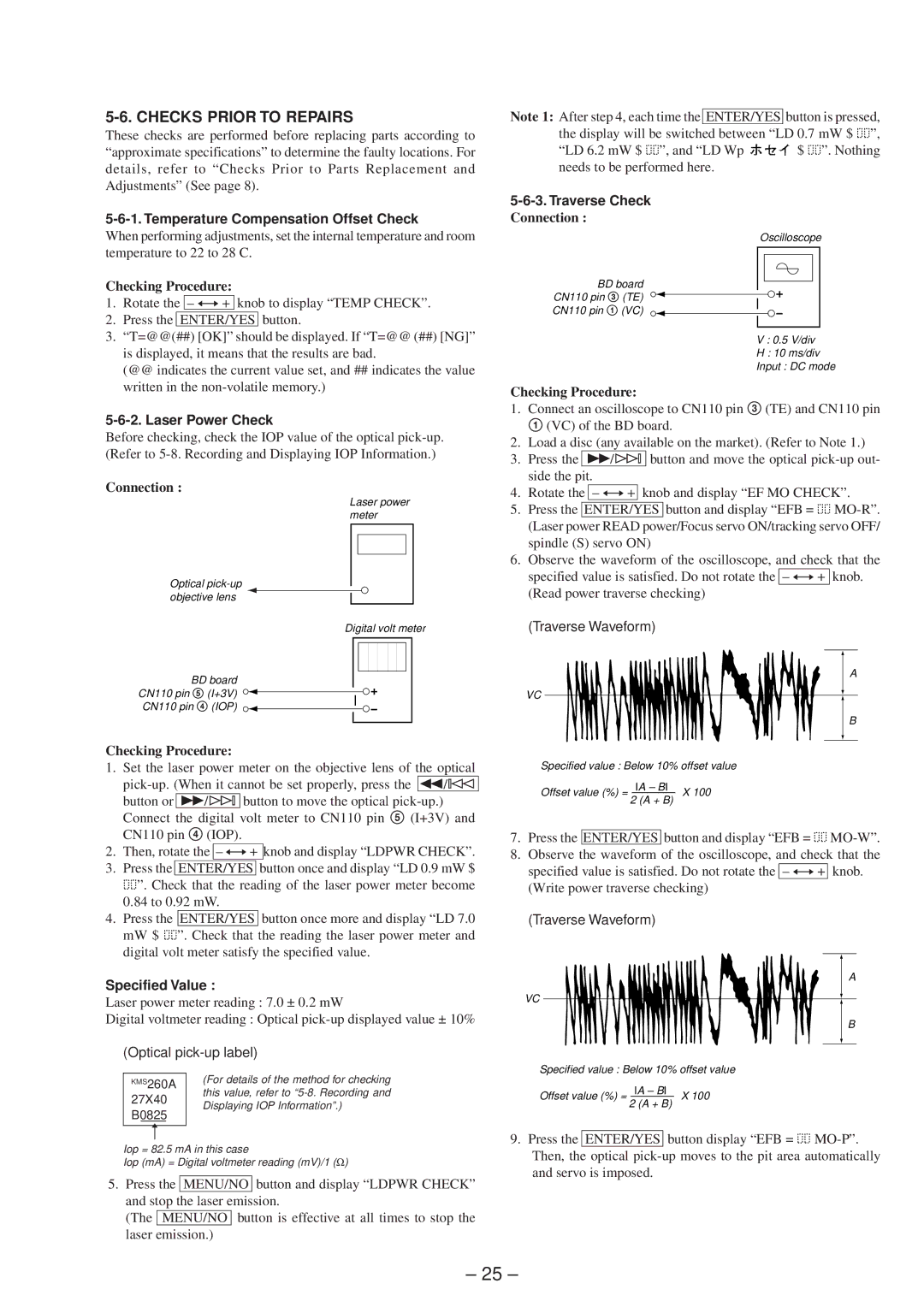
5-6-3. Traverse Check
Connection :
Oscilloscope
BD board
CN110 pin 3 (TE)
CN110 pin 1 (VC)
V : 0.5 V/div
H : 10 ms/div
Input : DC mode
Checking Procedure:
1.Connect an oscilloscope to CN110 pin 3 (TE) and CN110 pin 1 (VC) of the BD board.
2.Load a disc (any available on the market). (Refer to Note 1.)
3.Press the )/± button and move the optical
4.Rotate the
5.Press the ENTER/YES button and display “EFB = ![]()
![]()
6.Observe the waveform of the oscilloscope, and check that the specified value is satisfied. Do not rotate the
(Read power traverse checking)
(Traverse Waveform)
A
VC
B
Specified value : Below 10% offset value
Offset value (%) = IA – BI X 100 2 (A + B)
7.Press the ENTER/YES button and display “EFB = ![]()
![]()
8.Observe the waveform of the oscilloscope, and check that the specified value is satisfied. Do not rotate the
(Write power traverse checking)
(Traverse Waveform)
A
VC
B
Specified value : Below 10% offset value
Offset value (%) = IA – BI X 100 2 (A + B)
9.Press the ENTER/YES button display “EFB = ![]()
![]()
– 25 –