MZ-E501
SECTION 4
TEST MODE
4-1. GENERAL
•When entered in the TEST MODE, this set provides the Overall Adjustment mode which allows CD and MO discs to be auto- matically adjusted. In the Overall Adjustment mode, the system discriminates between CD and MO discs, performs adjustments in sequence automatically, and displays the faulty location if any fault is found. In the Manual mode, selected adjustments can be performed automatically.
•The attached remote control is used to operate the TEST MODE. Unless otherwise specified in the text, the key means that on the remote control.
4-2. SETTING THE TEST MODE
4-2-1. How to set the TEST MODE
To set the TEST MODE, two methods are available.
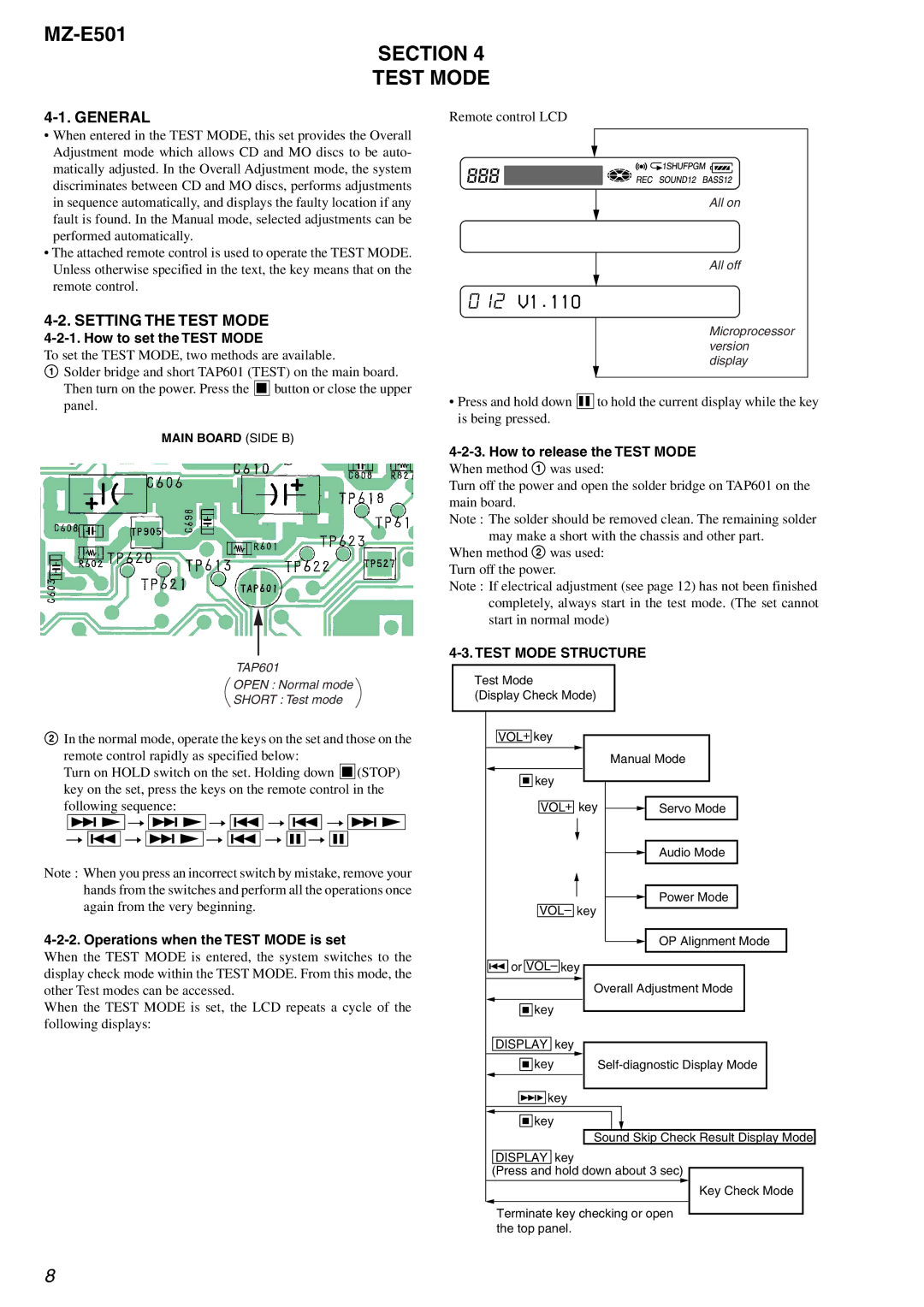
1Solder bridge and short TAP601 (TEST) on the main board. Then turn on the power. Press the x button or close the upper panel.
MAIN BOARD (SIDE B)
TAP601
OPEN : Normal mode
SHORT : Test mode
2In the normal mode, operate the keys on the set and those on the remote control rapidly as specified below:
Turn on HOLD switch on the set. Holding down x (STOP) key on the set, press the keys on the remote control in the following sequence:
>N t > N t . t . t > N t . t > N t . t X t X
Note : When you press an incorrect switch by mistake, remove your hands from the switches and perform all the operations once again from the very beginning.
4-2-2. Operations when the TEST MODE is set
When the TEST MODE is entered, the system switches to the display check mode within the TEST MODE. From this mode, the other Test modes can be accessed.
When the TEST MODE is set, the LCD repeats a cycle of the following displays:
Remote control LCD
All on
All off
012V1.110
Microprocessor version display
•Press and hold down X to hold the current display while the key is being pressed.
4-2-3. How to release the TEST MODE
When method 1 was used:
Turn off the power and open the solder bridge on TAP601 on the main board.
Note : The solder should be removed clean. The remaining solder may make a short with the chassis and other part.
When method 2 was used: Turn off the power.
Note : If electrical adjustment (see page 12) has not been finished completely, always start in the test mode. (The set cannot start in normal mode)
4-3. TEST MODE STRUCTURE
Test Mode
(Display Check Mode)
VOL+ key |
|
|
|
| Manual Mode |
x key |
|
|
VOL+ key | Servo Mode | |
|
| Audio Mode |
VOL– key | Power Mode | |
| ||
|
| OP Alignment Mode |
. or VOL– key |
|
|
| Overall Adjustment Mode | |
x |
|
|
key |
|
|
DISPLAY key |
|
|
x | ||
key | ||
>B key |
|
|
x key |
|
|
| Sound Skip Check Result Display Mode | |
DISPLAY key |
|
|
(Press and hold down about 3 sec) | ||
|
| Key Check Mode |
Terminate key checking or open the top panel.
8