MZ-E501
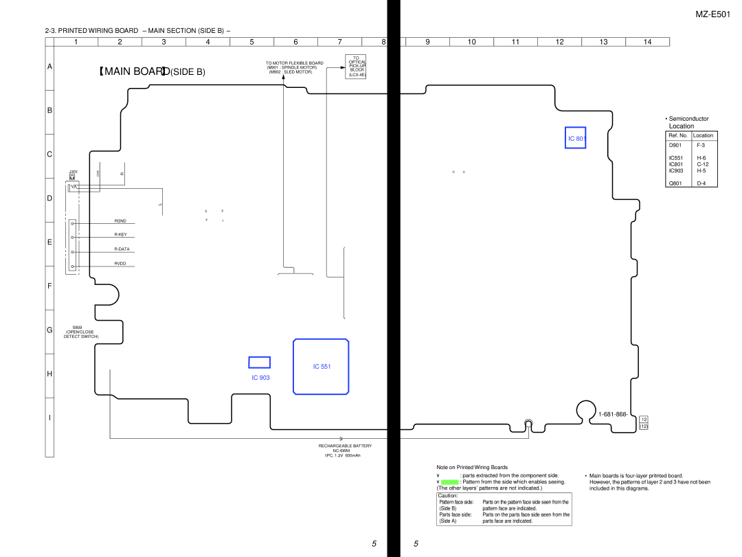
2-3. PRINTED WIRING BOARD – MAIN SECTION (SIDE B) –
1 | 2 |
| 3 |
| 4 | 5 |
| 6 | 7 |
| 8 | 9 | 10 | 11 | 12 | 13 | 14 | |
|
|
|
|
|
|
|
|
|
|
|
|
|
|
|
|
|
|
|
|
|
|
|
|
|
|
|
|
| TO |
|
|
|
|
|
|
| |
A |
|
|
|
|
|
| TO MOTOR FLEXIBLE BOARD |
| OPTICAL |
|
|
|
|
|
|
| ||
MAIN BOARD |
| (SIDE B) |
| (M901 : SPINDLE MOTOR) |
|
|
|
|
|
|
|
| ||||||
|
|
|
|
|
|
|
|
|
|
|
|
| ||||||
|
|
|
|
|
|
| (M902 : SLED MOTOR) |
| BLOCK |
|
|
|
|
|
|
| ||
|
|
|
|
|
|
|
|
|
|
|
|
|
|
|
|
| ||
|
|
|
|
|
|
|
|
|
|
|
|
|
|
|
|
|
|
|
B
IC 801
C |
|
|
|
|
J301 | COM | R |
|
|
|
|
| ||
D |
|
| L |
|
|
|
|
| |
|
|
| 5 | 3 |
|
| RGND | 4 | 1 |
|
|
|
| |
E |
|
|
|
|
|
|
|
| |
|
| RVDD |
|
|
F
G | S809 |
(OPEN/CLOSE | |
| DETECT SWITCH) |
IC 551
H | IC 903 |
|
I |
|
12 | |
| (12) |
| RECHARGEABLE BATTERY |
| |
| 1PC, 1.2V 600mAh |
•Semiconductor
Location
Ref. No. | Location |
|
|
D901 | |
IC551 | |
IC801 | |
IC903 | |
Q801 |
Note on Printed Wiring Boards
•X : parts extracted from the component side.
•![]() : Pattern from the side which enables seeing. (The other layers' patterns are not indicated.)
: Pattern from the side which enables seeing. (The other layers' patterns are not indicated.)
Caution: |
|
Pattern face side: | Parts on the pattern face side seen from the |
(Side B) | pattern face are indicated. |
Parts face side: | Parts on the parts face side seen from the |
(Side A) | parts face are indicated. |
|
|
•Main boards is
However, the patterns of layer 2 and 3 have not been included in this diagrams.
55