Operating Instructions Mode d’emploi Bedienungsanleitung
Digital Audio Tape Deck
859-278-121
Information
Varning
Varoitus
Table of Contents
Unpacking
Before using the remote
When to replace the batteries
Rack Mounting
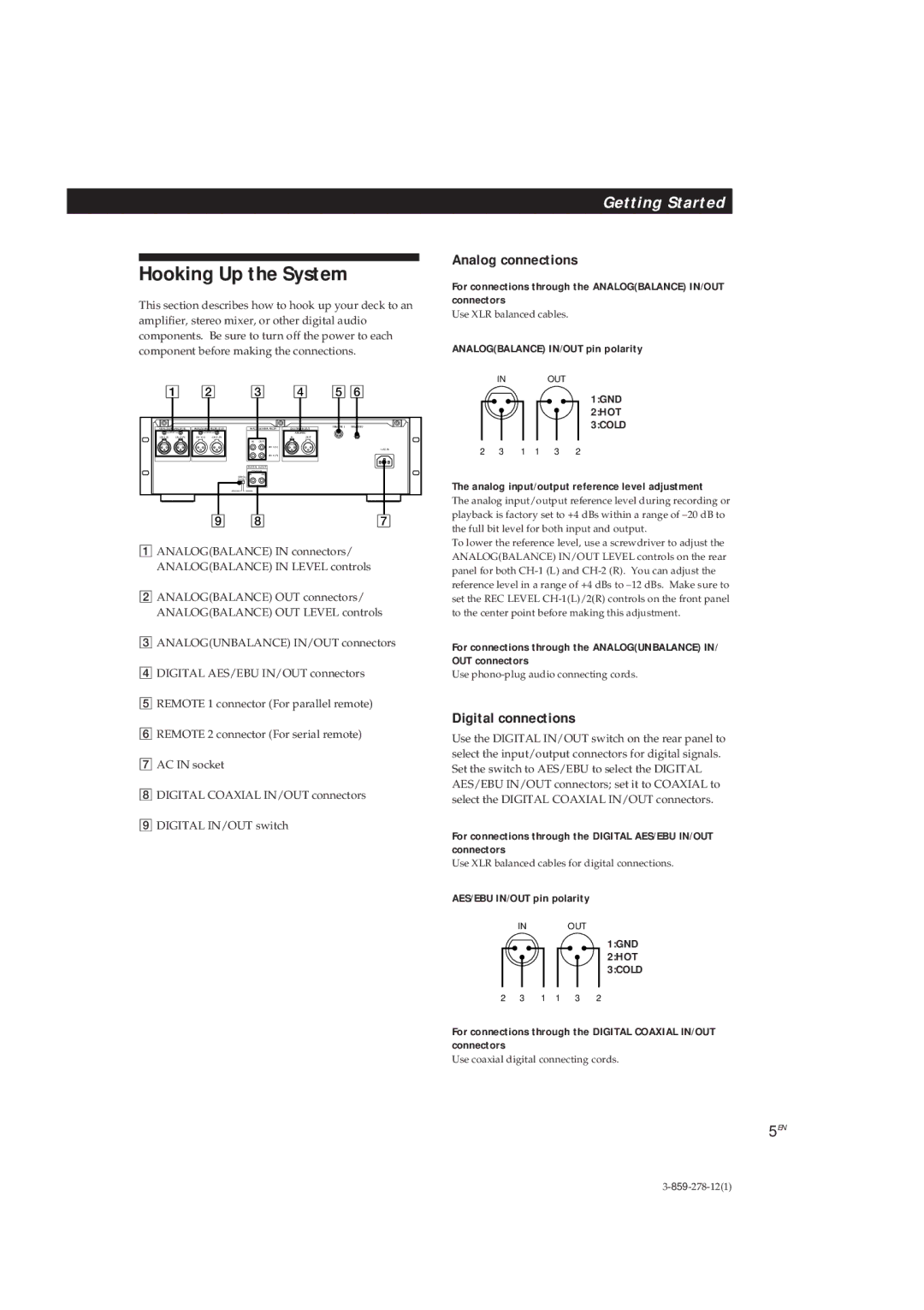
Hooking Up the System
Analog connections
Digital connections
Digital Interface
Connecting AC power cord
Digital input and output connectors
Other connections
Writing start IDs automatically during recording
Digital signal lock range
Signal format
Code
For more accurate time recordings
Setting the Clock
To display the date or time
Menu
See pages 5 and 6 for hookup information To use headphones
Press
OPEN/CLOSE
See pages 5 and 6 for hookup information
To record through Positions of the switches
10EN
Input Analog Input Digital IN/OUT
11EN
To adjust the recording level more accurately
To reset the margin indication
If Unlock appears in the display
Absolute time codes
Things You Should Know Before Recording
Lead-in area
If Emphasis appears in the display
13EN
Setting the Recording Mode
Using the SBM Super Bit Mapping Function
Recmode
When you press the REC r button while in a blank section
14EN
Play REC r REC Mute R
Fading out
Fade-in/Fade-out Recording Fader PCM-R700 Only
Fading
15EN
About the Display
To reset the tape running time
When Date appears in the display
ERR appears in the display for 5 seconds or more
Locating a Track AMS*/Direct Access
Locating a Point Shuttle Play/ Mark & Locate
17EN
Playing a track repeatedly
Playing Tracks Repeatedly Repeat Play
Playing all tracks repeatedly
18EN
About Sub Codes
Fade-in/Fade-out Playback Fader PCM-R700 only
Specifying the first program number to be assigned
Writing Start IDs During Recording
Writing program numbers during recording
Writing start IDs manually during recording
Writing skip IDs manually during recording
Writing Skip IDs During Recording
Writing Sub Codes During Playback
Accurate positioning of sub codes Rehearsal function
Adjusting the Position of an Existing Start ID
22EN
Start ID Rehearsal
You can erase an ID even when it is not displayed
Erasing Sub Codes
23EN
Menu descriptions
Making menu settings
Menu Operations
24EN
25EN
DAT
Datehour Date Hour
Optional Remote RM-D750
Playing tracks in the order you want RMS* Play
Locating a track by scanning each track Music Scan
More accurate positioning of the end ID
Writing and Erasing an End ID
Writing an end ID during recording
Erasing the end ID
Using the Remote 1 connector
28EN
MODE1 MODE2
Cleaning the cabinet, panel and controls
Precautions
Cleaning
Cleaning the head and tape path
Troubleshooting
Display Messages
30EN
31EN
Specifications
32EN
Index
U, V, W, X, Y, Z
Names of controls
Switches
34EN
35EN
Bienvenue
Au sujet de ce mode d’emploi
Fonctions additionnelles avec la télécommande en option
Pour la clientèle au Canada
Fonctions élaborées pour la lecture
Opérations avec la télécommande en option
Préparatifs
Inscription de sous-codes
Installation dans un rack
Mise en place des piles dans la télécommande
Déballage
Raccordements
Connexions analogiques
Raccordements numériques
Branchement du cordon d’alimentation
Interface numérique
Autres raccordements
Connecteurs d’entrée et de sortie numérique
Plage de verrouillage du signal numérique
’entrée Signal code
De catégorie
Réglage de l’horloge
Pour afficher la date ou l’heure
Pour que l’heure soit enregistrée avec précision
Pour Appuyez sur
Pour enregistrer via Position des sélecteurs
10F
Voir les pages 5 et 6 pour les raccordements
Analog Input Digital IN/OUT
Si le niveau dépasse 0 dB
11F
Si Unlock apparaît dans l’affichage
Enregistrement possible l’orifice est fermé
Codes de temps absolu
Zone d’amorçage
Si Emphasis apparaît sur l’affichage
12F
Utilisation de la fonction SBM Super Bit Mapping
Réglage du mode d’enregistrement
Compteur en mode longue durée
13F
14F
Si vous appuyez sur la touche REC rlors d’un passage vierge
15F
Ouverture en fondu
Fermeture en fondu
Pour écouter la source de programme
Ou plus
Propos de l’affichage
ERR apparaît dans l’affichage 5 secondes
16F
Pour localiser Procédez comme suit
Localisation d’une plage AMS*/ accès direct
17F
Vitesse de lecture en Shuttle Play
Répétition d’une plage
Répétition de plages lecture répétée
Répétition de toutes les plages
18F
Identifiant de début
Identifiant de fin quand la télécommande est utilisée
Utilisation des sous-codes
Numéro de programme
20F
Quand un numéro de programme est affiché
Touches numériques
Inscription d’identifiants de saut pendant l’enregistrement
Positionnement précis des sous-codes fonction d’essai
21F
22F
23F
Effacement de sous-codes
Renumérotation automatique des numéros de programme
Vous pouvez effacer un code même s’il n’est pas affiché
Description des menus
Opérations de menu
Réglages de menu
24F
25F
La télécommande RM-D750 en option
Lecture de plages dans l’ordre choisi RMS* Play
26F
Positionnement plus précis de l’identifiant de fin
Inscription et effacement d’un identifiant de fin
Effacement de l’identifiant de fin
27F
Utilisation du connecteur Remote
28F
Nettoyage
Nettoyage du coffret, du panneau et des commandes
Précautions
Nettoyage de la tête et du parcours de la bande
Messages sur l’affichage
Guide de dépannage
30F
Impossible d’inscrire les codes de temps absolu
31F
Impossible de localiser une plage
La bande s’arrête brusquement
Spécifications
32F
V, W, X, Y
33F
Nomenclature
34F
35F
Willkommen Zu dieser Anleitung
Gemeinsame Merkmale
Zum Aufbau dieses Handbuchs
Fortgeschrittener Wiedergabebetrieb
Vorbereitungen
Wiedergabe Aufnahme Fortgeschrittener Aufnahmebetrieb
Setzen von Subcodes
Nach dem Auspacken Gestellmontage
Einlegen der Batterien in die Fernbedienung
Anschlüsse
Analoge Anschlüsse
Digitale Anschlüsse
Digitale Schnittstelle
Start
Synchronisierbereich für Digitalsignale
Automatisches Setzen von Startcodes bei der Aufnahme
Code b
Einstellen von Uhrzeit und Datum
Aufrufen von Datum oder Uhrzeit
Damit stets die richtige Uhrzeit aufgezeichnet wird
Anschluß eines Kopfhörers
Zum Drücken Sie
Mit dem Fenster nach oben
10D
Für Aufnahme über Schalter-Einstellungen
Wenn der Pegel 0 dB überschreitet
11D
Falls „UNLOCK im Display angezeigt wird
Zum Rückstellen der MARGIN-Anzeige
Wissenswertes zur Aufnahme
Einstellen des Aufnahmemodus
REC Mode
Verwendung der Super-Bit Mapping-Funktion SBM
13D
14D
Verwendung der Ende Suchfunktion
Einfügen einer Leerstelle während der Aufnahme Record Mute
Zum Einfügen längerer Leerstellen als im Menü eingestellt
Einblenden
Um das Eingangssignal zu hören
Ein- und Ausblenden der Aufnahme Fader Nur PCM-R700
Ausblenden
16D
Über das Display
Wenn Emphasis im Display angezeigt wird
Rückstellen der Bandlaufzeit
Titelsuche AMS*/Direktsuche
Ansteuern einer Bandstelle Shuttle Play/Mark & Locate
17D
Zum Wiederholen aller Titel
Überspringen von markierten Bandteilen Skip Play- Funktion
Wiederholspielbetrieb Repeat-Funktion
Zum Wiederholen eines einzelnen Titels
Startcodes Start ID
Die verschiedenen Subcodes
Ein- und Ausblenden der Wiedergabe Fader nur PCM-R700
Programmnummern
20D
Setzen von Startcodes während der Aufnahme
Manuelles Setzen von Startcodes während der Aufnahme
Wenn eine Programmnummer angezeigt ist
Setzen von Subcodes während der Wiedergabe
Exaktes Positionieren von Subcodes Rehearsal-Funktion
21D
Feinkorrektur der Position eines existierenden Startcodes
22D
REW
Löschen von Subcodes
23D
Beschreibung der Menüs
Menü-Steuerung
Vornahme von Menü-Einstellungen
24D
25D
Titelsuche mit der Anspielfunktion Music Scan
Fernbedienung RM-D750 Sonderzubehör
Programm-Wiedergabe RMS* Play
26D
Feineinstellen der Endcode-Position
Setzen und Löschen eines Endcodes
Setzen eines Endcodes während der Aufnahme
Löschen des Endcodes
Benutzung der Remote 1-Buchse
28D
Reinigen des Tonkopfes und des Bandpfades
Zur besonderen Beachtung
Reinigung
29D
Meldungen im Display
Störungsüberprüfungen
30D
31D
Technische Daten
32D
Y, Z
Stichwortverzeichnis
I, J
33D
Bezeichnung der Bedienungselemente
34D
35D

 2
2
 3
3
 4
4
 5
5
 6
6