![]() Upper Case
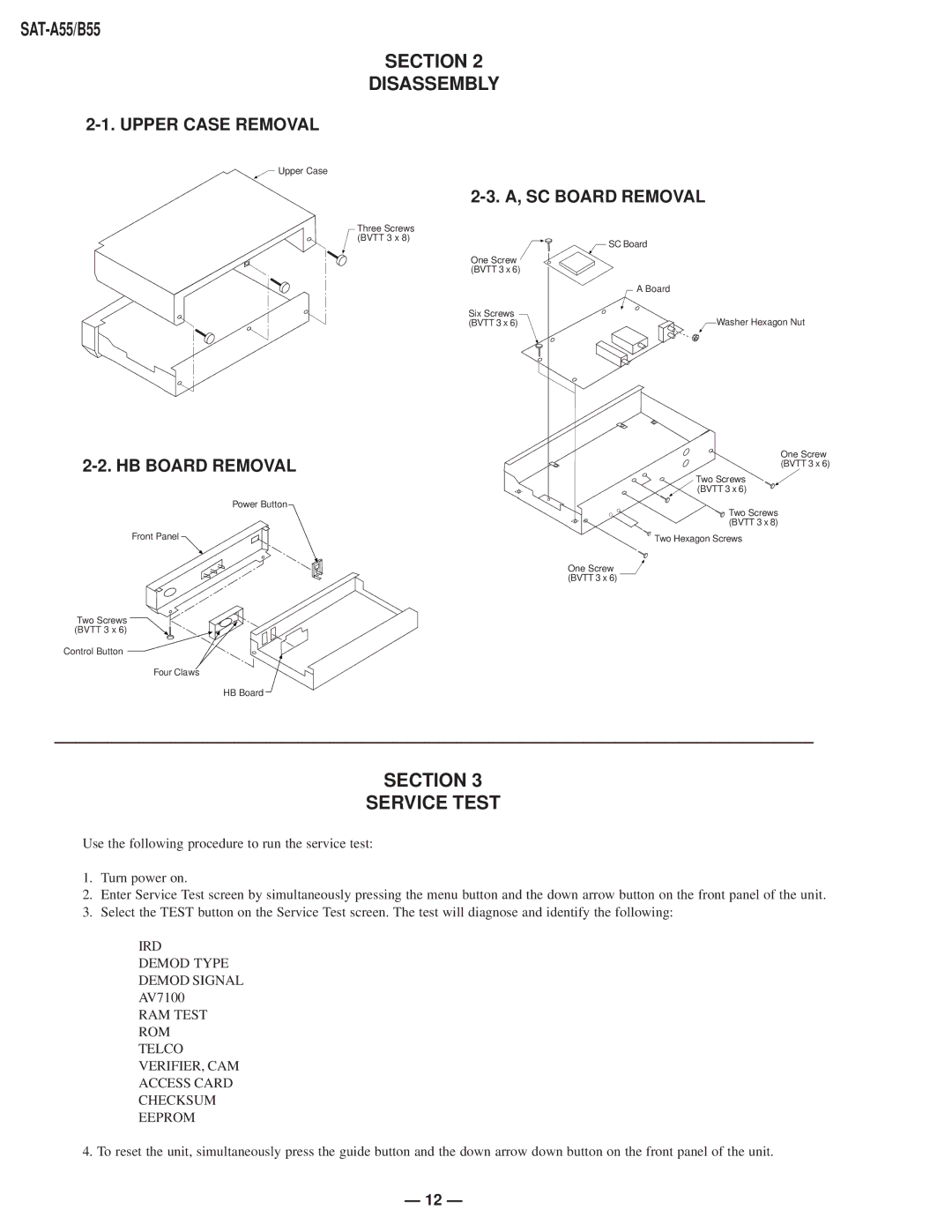
Upper Case
Power Button
Front Panel ![]()
Two Screws (BVTT 3 x 6)
Control Button
Four Claws
HB Board
SECTION 2
DISASSEMBLY
2-3. A, SC BOARD REMOVAL
Three Screws |
|
(BVTT 3 x 8) | SC Board |
| |
One Screw |
|
(BVTT 3 x 6) |
|
| A Board |
Six Screws | Washer Hexagon Nut |
(BVTT 3 x 6) |
One Screw (BVTT 3 x 6)
Two Screws (BVTT 3 x 6)
![]() Two Screws (BVTT 3 x 8)
Two Screws (BVTT 3 x 8)
Two Hexagon Screws
One Screw ![]() (BVTT 3 x 6)
(BVTT 3 x 6)
SECTION 3
SERVICE TEST
Use the following procedure to run the service test:
1.Turn power on.
2.Enter Service Test screen by simultaneously pressing the menu button and the down arrow button on the front panel of the unit.
3.Select the TEST button on the Service Test screen. The test will diagnose and identify the following:
IRD
DEMOD TYPE
DEMOD SIGNAL
AV7100
RAM TEST
ROM
TELCO
VERIFIER, CAM
ACCESS CARD
CHECKSUM
EEPROM
4. To reset the unit, simultaneously press the guide button and the down arrow down button on the front panel of the unit.
— 12 —