A
SC
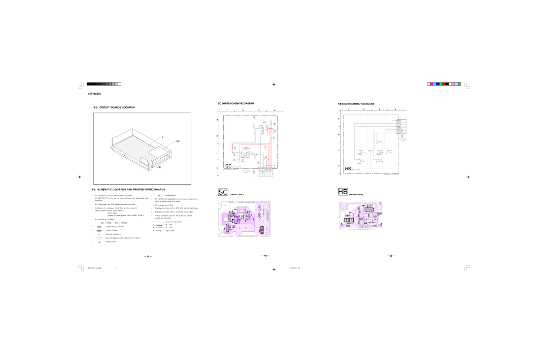
![]() HB
HB
SC BOARD SCHEMATIC DIAGRAM
SC
HB BOARD SCHEMATIC DIAGRAM
HB
•All capacitors are in μF unless otherwise noted.
pF: μμF 50 WV or less are not indicated except for electrolytic and tantalums.
•All electrolytics are 50V unless otherwise specified.
•Indication of resistance, which does not have one for rating electrical power, is as follows:
Pitch: 5mm
Rating electrical power 1/4W (CHIP: 1/10W)
•All resistors are in ohms.
KΩ = 1000Ω MΩ = 1000KΩ
•![]() : nonflammable resistor
: nonflammable resistor
•![]() : fusible resistor
: fusible resistor
• | : internal component |
• | : |
•All variable and adjustable resistors have characteristic curve B, unless otherwise noted.
•All voltages are in Volts
•Readings are taken with a 10M ohm digital multimeter.
•Readings are taken with a
•Voltage variations may be noted due to normal production tolerance.
•* : cannot be measured
•: B + Line
•
•![]() : Signal path
: Signal path
[SMART CARD]
[FRONT PANEL]
• |
| : | panel designation and adjustment for repair |
• | : | ||
— 18 —
— 19 —
— 20 —
1. SATA50 SC H bd.p65 | 1 | 1/12/00, 3:46 PM |