FOR SATELLITE ANTENNAS:
SAT-A55/B55
Input Frequency
Output Frequency
Output Connector
Power Consumption
Supply Voltage
Dimensions (w/h/d)
Weight
12.2- 12.7 GHz
950 - 1450 MHz
3.0 W max.
DC + 10.5 - 14.0 V for RHCP DC + 15.5 - 21.0 V for LHCP
185/8 x 31 x 185/16 inches
473 x 787 x 643 mm
8 lbs 6 oz (3.8 kg)
Supplied | Weatherboot 2pcs |
|
Accessories | Signal Seeker 1pc |
|
| ||
| Bolt for Ground Terminal 1pc | |
| Bolt for LNB Support Arm 2pcs | |
Optional | Installation Kit | |
Accessories | Amplifier | |
| Diplexer | |
| Voltage Switch | |
|
| |
| Distribution System | |
| Coaxial Cable 25' | |
| Coaxial Cable 75' | |
| Flat Cable | |
SAFETY CHECK-OUT
1.Check the area of your repair for unsoldered or poorly- soldered connections. Check the entire board surface for solder splashes and bridges.
2.Check the interboard wiring to ensure that no wires are “pinched” or contact
3.Check that all control knobs, shields, covers, ground straps, and mounting hardware have been replaced. Be absolutely certain that you have replaced all the insulators.
4.Look for unauthorized replacement parts, particularly transistors, that were installed during a previous repair. Point them out to the customer and recommend their replacement.
LEAKAGE TEST
The AC leakage from any exposed metal part to earth ground and from all exposed metal parts to any exposed metal part having a return to chassis, must not exceed 0.5 mA (500 microamperes). Leakage current can be mea- sured by any one of three methods.
1.A commercial leakage tester, such as the Simpson 229 or RCA
2.A
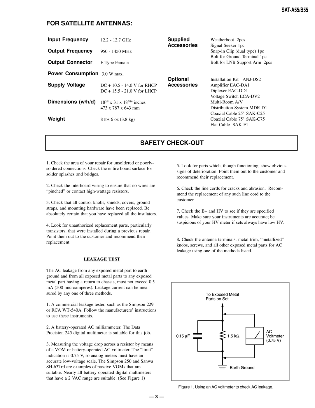
3.Measuring the voltage drop across a resistor by means of a VOM or
5.Look for parts which, though functioning, show obvious signs of deterioration. Point them out to the customer and recommend their replacement.
6.Check the line cords for cracks and abrasion. Recom- mend the replacement of any such line cord to the customer.
7.Check the B+ and HV to see if they are specified values. Make sure your instruments are accurate; be suspicious of your HV meter if sets always have low HV.
8.Check the antenna terminals, metal trim, “metallized” knobs, screws, and all other exposed metal parts for AC leakage using one of the methods listed.
Figure 1. Using an AC voltmeter to check AC leakage.
— 3 —