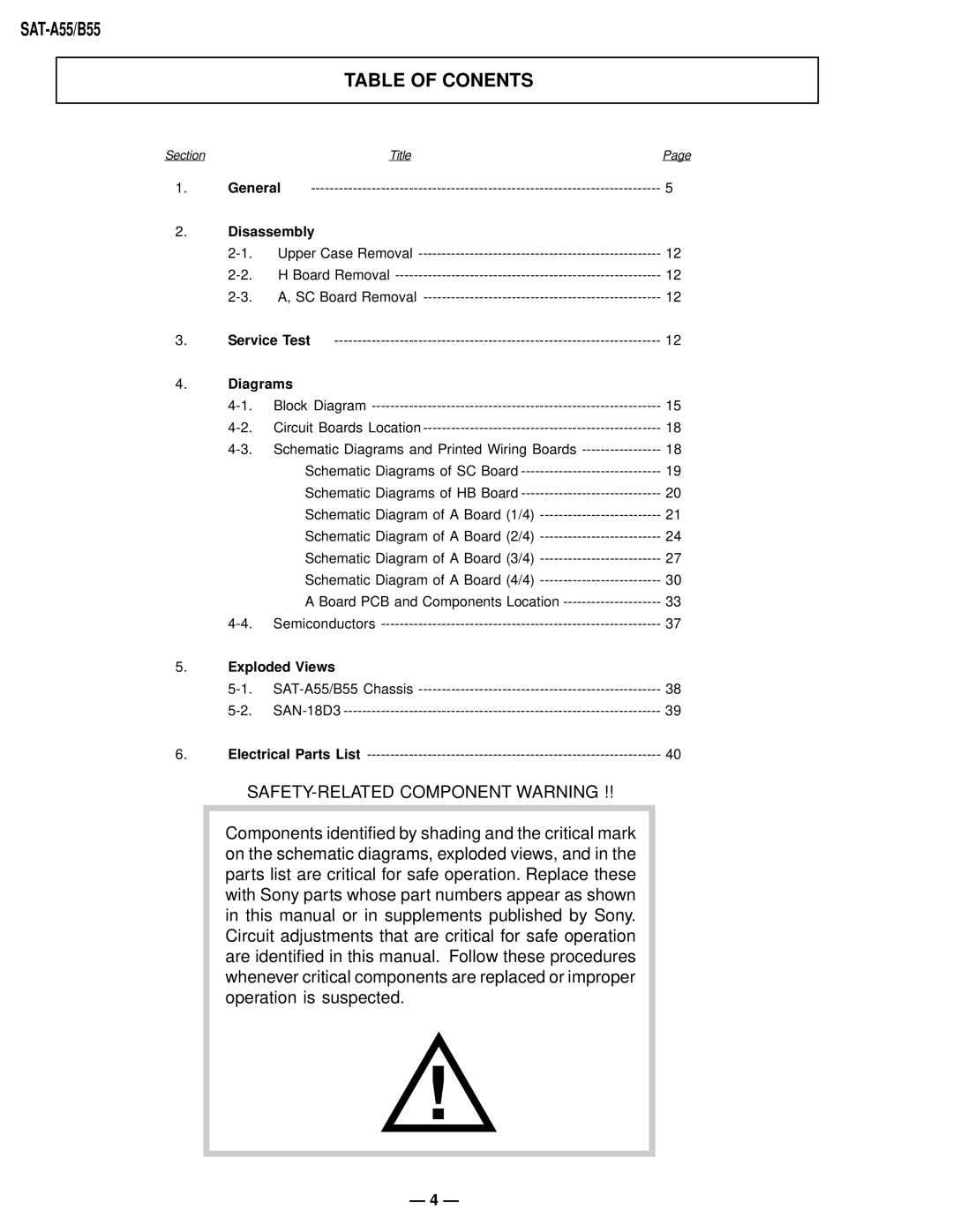
TABLE OF CONENTS
Section | Title | Page |
1. | General | 5 |
2.Disassembly
| Upper Case Removal | 12 | |
| H Board Removal | 12 | |
| A, SC Board Removal | 12 | |
3. | Service Test | 12 | |
4.Diagrams
Block Diagram | 15 | |
Circuit Boards Location | 18 | |
Schematic Diagrams and Printed Wiring Boards | 18 | |
| Schematic Diagrams of SC Board | 19 |
| Schematic Diagrams of HB Board | 20 |
| Schematic Diagram of A Board (1/4) | 21 |
| Schematic Diagram of A Board (2/4) | 24 |
| Schematic Diagram of A Board (3/4) | 27 |
| Schematic Diagram of A Board (4/4) | 30 |
| A Board PCB and Components Location | 33 |
Semiconductors | 37 |
5.Exploded Views
|
| 38 | |
|
| 39 | |
6. | Electrical Parts List | 40 | |
SAFETY-RELATED COMPONENT WARNING !!
Components identified by shading and the critical mark on the schematic diagrams, exploded views, and in the parts list are critical for safe operation. Replace these with Sony parts whose part numbers appear as shown in this manual or in supplements published by Sony. Circuit adjustments that are critical for safe operation are identified in this manual. Follow these procedures whenever critical components are replaced or improper operation is suspected.
!
— 4 —
