OUTPUT WAVEFORM TIMING CHART
 (XC-ES50/EI50/ES30/EI30(EIA)) 
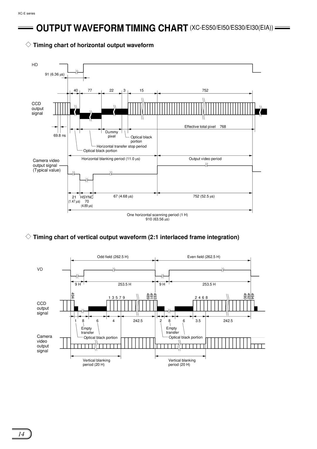
 Timing chart of horizontal output waveform
HD
91 (6.36 ∝s)
40 | 77 | 22 | 3 | 15 | 752 |
CCD output signal
|
|
|
|
|
|
|
|
|
|
|
|
|
|
|
|
|
|
|
| Effective total pixel 768 |
|
|
|
|
|
|
|
|
|
|
|
|
|
|
|
|
|
|
|
|
|
|
|
| |
|
|
|
|
|
|
|
|
|
|
|
|
|
|
|
|
|
|
|
|
|
| |
| 69.8 ns |
|
|
|
|
| Dummy |
|
|
|
|
|
|
|
| |||||||
|
|
|
|
|
|
|
| |||||||||||||||
|
|
|
|
|
| pixel |
|
| Optical black |
|
|
| ||||||||||
|
|
|
|
|
|
|
|
|
|
| ||||||||||||
|
|
|
|
|
|
|
|
|
|
|
|
|
|
|
|
|
|
| portion |
|
|
|
|
|
|
|
|
|
|
|
|
|
|
|
|
| Horizontal transfer stop period |
|
|
| |||||
|
|
|
|
|
|
|
|
|
|
|
|
|
|
|
|
| ||||||
|
|
|
|
|
|
|
|
|
|
| Optical black portion |
|
|
|
|
| ||||||
|
|
|
|
|
|
|
|
|
|
|
|
|
|
|
| |||||||
|
|
|
|
|
|
|
|
|
|
|
|
|
|
|
|
|
|
|
| |||
Camera video |
| Horizontal blanking period (11.0 ∝s) | Output video period |
|
| |||||||||||||||||
|
|
|
|
|
|
|
|
|
|
|
|
|
| |||||||||
output signal |
|
|
|
|
|
|
|
|
|
|
|
|
|
|
|
|
|
|
|
| ||
(Typical value) |
|
|
|
|
|
|
|
|
|
|
|
|
|
|
|
|
| |||||
|
|
|
|
|
|
|
|
|
|
|
|
|
|
|
|
|
|
|
|
|
|
|
|
|
|
|
|
|
|
|
|
|
|
|
|
|
|
|
|
|
|
|
|
|
|
21 | HSYNC | 67 (4.68 ∝s) | 752 (52.5 ∝s) |
(1.47 ∝s) | 70 |
|
|
(4.89 ∝s)
One horizontal scanning period (1 H)
910 (63.56 ∝s)
![]() Timing chart of vertical output waveform (2:1 interlaced frame integration)
Timing chart of vertical output waveform (2:1 interlaced frame integration)
|
| Odd field (262.5 H) |
|
|
|
| Even field (262.5 H) |
|
|
| |
VD |
|
|
|
|
|
|
|
|
|
|
|
9 H |
|
| 253.5 H |
| 9 H |
|
| 253.5 H |
|
|
|
494 |
|
| 1 3 5 7 9 | 493 491 489 |
|
|
| 2 4 6 8 | 490 | 492 | 494 |
CCD |
|
|
|
|
|
|
|
|
|
|
|
output |
|
|
|
|
|
|
|
|
|
|
|
signal |
|
|
|
|
|
|
|
|
|
|
|
1 | 8 | 6 | 4 | 242.5 | 2 | 8 | 6 | 3.5 | 242.5 |
|
|
| Empty |
|
|
|
| Empty |
|
|
|
|
|
Camera | transfer |
|
|
|
| transfer |
|
|
|
|
|
Optical black portion |
|
| Optical black portion |
|
|
| |||||
video |
|
|
|
|
|
|
|
|
|
|
|
output |
|
|
|
|
|
|
|
|
|
|
|
signal |
|
|
|
|
|
|
|
|
|
|
|
Vertical blanking | Vertical blanking |
period (20 H) | period (20 H) |
14