Hardware Setup |
|
Step 13. 5V Stand-by indicator LED (LED 1)
This LED is lit whenever the 5V Standby voltage coming from the ATX powersupply is available. If you have connected your ATX powersupply to the mains, LED 1 should be lit.
Step 14. External Suspend Button (JP1)
Some cases come with a suspend button, insert the plug into JP1. In addition to this button, the system can also enter the suspend mode through your OS.
Note: Suspend mode only functions if your Power Management mode is APM. Make sure that the BIOS setting for Power Management is APM. Windows 98 can be installed with ACPI Power Management (default is APM), in this case suspend mode will not function either.
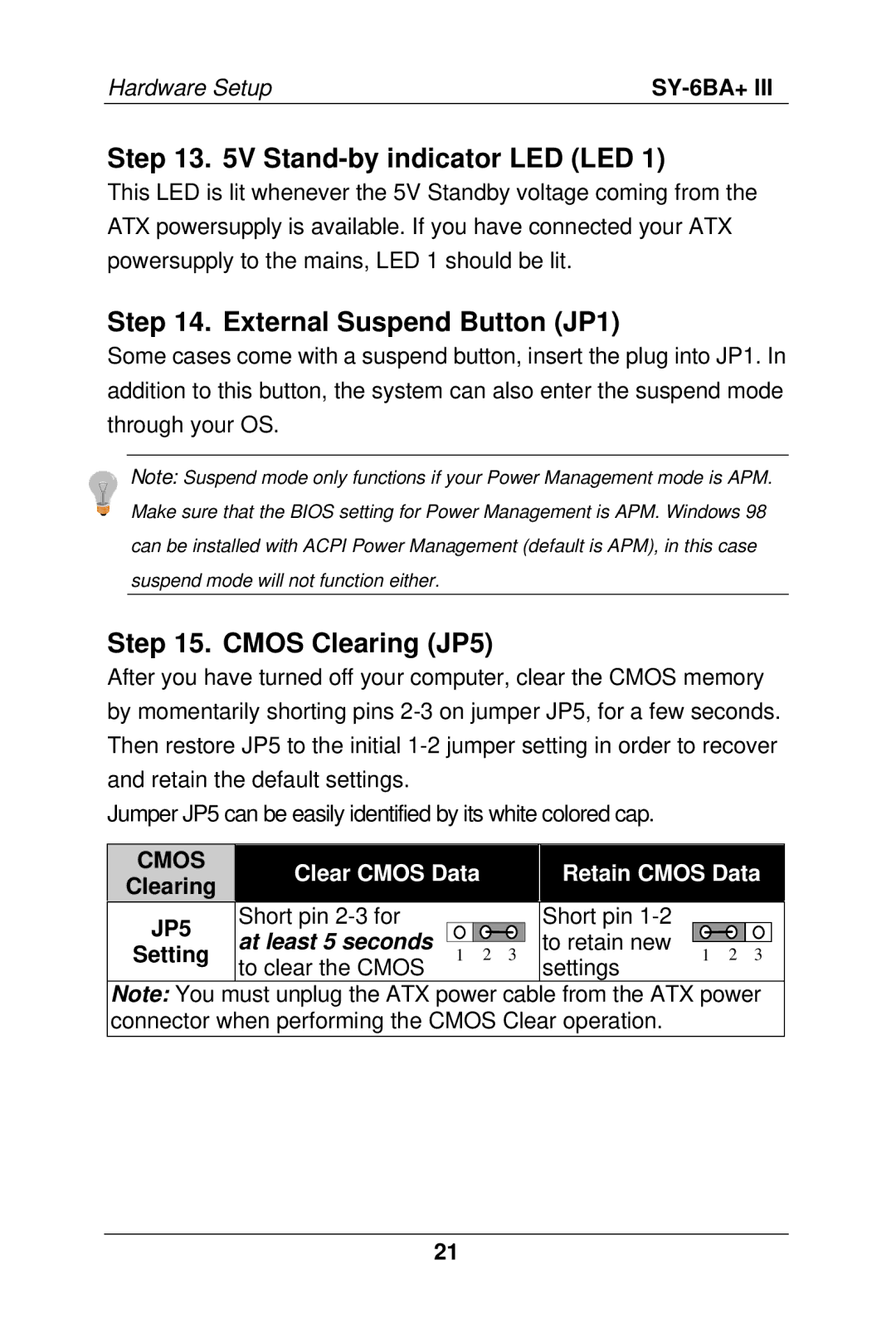
Step 15. CMOS Clearing (JP5)
After you have turned off your computer, clear the CMOS memory by momentarily shorting pins
Jumper JP5 can be easily identified by its white colored cap.
Clear CMOS Data
Retain CMOS Data
JP5 | Short pin |
|
|
|
| Short pin |
|
|
|
|
at least 5 seconds |
|
|
|
| to retain new |
|
|
|
| |
Setting | 1 | 2 | 3 |
| 1 | 2 | 3 |
| ||
to clear the CMOS |
| settings |
| |||||||
|
|
|
|
|
|
|
|
|
Note: You must unplug the ATX power cable from the ATX power connector when performing the CMOS Clear operation.
21