SY-7IWA-F
Version
SY-7IWA-F
Edition August
7IWA-F Serial
Table of Contents
SY-7IWA-F
KEY Features
Introduction
SY-7IWA-F
Electrostatic Discharge Precautions
Handling the Motherboard
SY-7IWA-F Motherboard Layout
Intel
SY-7IWA-F Motherboard Components
SY-7IWA-F
Chipset
New design with big benefits
SY-7IWA-F
Features Benefits
Product Highlights
Product Package
Accelerated Graphics Port A.G.P
Universal Serial Bus USB
¿Note
IDE Support
Serial Ports
Real-Time Clock, Cmos SRAM, and Battery
I/O Interface Controller
Parallel Port
Diskette Drive Controller
4 PS/2 Keyboard and Mouse Interface
Audio Subsystem
Audio Connector
CD Line in Connector
Hardware Monitor
Wake on LAN Technology
Chapter
Preparations
Unpacking the Motherboard
Begin the Installation
Installation Guide
CPU Installation
To install the CPU, follow the steps below
SY-7IWA-F
Sdram Memory Module Installation
Hardware Installation
Number Memory
Modules Double-sided Single-sided Single-sided² RAM Type
Motherboard Connector IDE Device Installation HDD, CD-ROM
IDE
Floppy Drive Installation
FDC
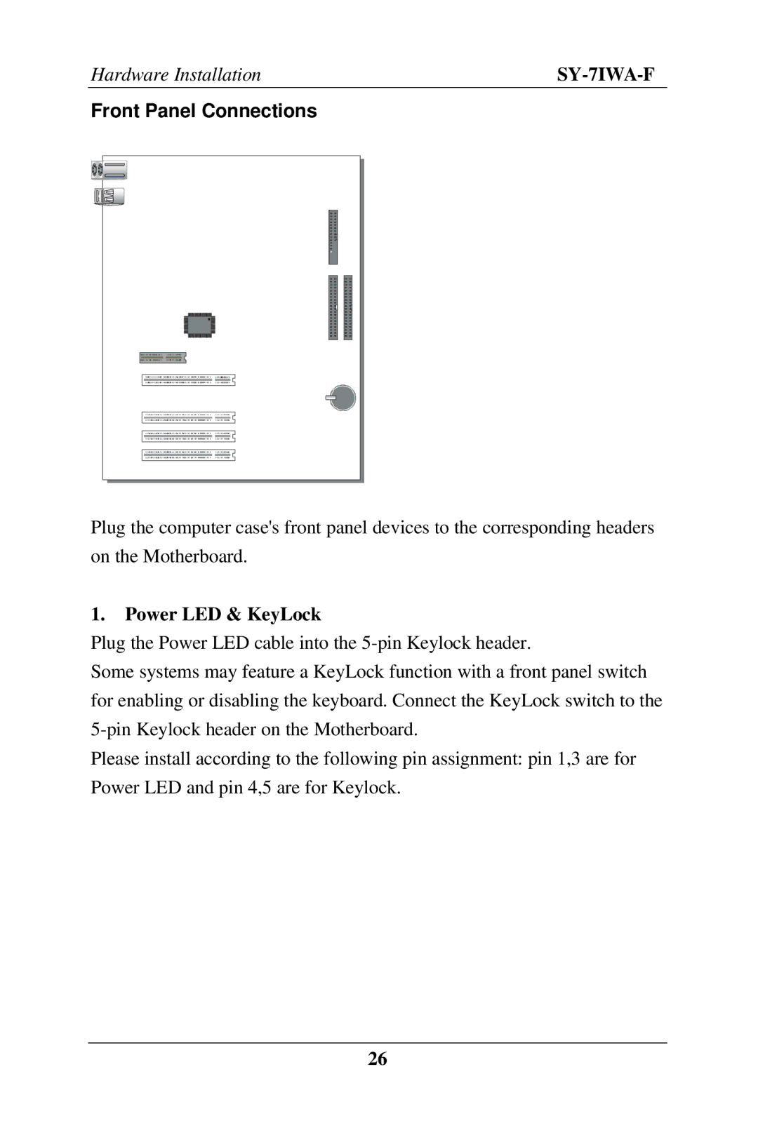
Power LED & KeyLock
Front Panel Connections
Reset
Speaker
Acpi LED
ATX Power On/Off Switch
IDE LED
Back Panel Connections
Parallel Port PRT
PS/2 Mouse
Universal Serial Bus USB1/USB2
Flat Panel Connector
VGA monitor connector
Onboard Joystick port/audio
Other Connections
Serial Port COM 1 and COM2
Wake-On-LAN JP44 Pin Assignment
Wake-On-LAN WOL
Infrared IR1
CD Line-in J10,J11
Cooling Fan Installation CPU Cooling Fan
CPU Cooling Fan Cpufan Pin Assignment
Power Cooling Fan
Chassis Cooling Fan
ATX Power Supply
AGP VGA Card
ATX Power
GND Ø Pay special care to the directionality
AMR Audio Modem Riser Connector
Manual Mode
Jumper Setting Set J6 &JP2 to configure CPU FSB Frequency
Auto Mode
JP2
Set JP9 for FWH Boot Block Write-Protect
Enable/Disable Power-On by Keyboard JP1
Power-On by Win 98 Hot Key USB
Keyboard JP11 Setting
CPU Core Voltage Adjust JP15, JP16
JP15 Setting JP16 Setting
Cmos Clearing JP5
JP5 Setting
Power On
Cmos Clearing
Quick Bios Setup
Cmos Setup Utility Copyright C 1984-1999 Award Software
Select Soyo Combo Feature
Select Standard Cmos Setup
Select Load Optimized Defaults
Select Save & Exit Setup
Troubleshooting at First Start
What should I do if the Motherboard refuses to start?
Power Off
Selecting items
Modifying selected items
Function Command Description
Save and Exit Setup
Exit Without Saving
Soyo Combo Setup
Soyo Combo Setup
Bios Setup Utility
Quick CPU Frequency Setup
2 L2 Cache Memory
System Boot Control Settings
Setting Description Smaa
System Boot Control Settings
Boot Other Device AC97 Audio/Modem Setting Description
Password
Setting Description
KB Power on
Hot Key Power
Standard Cmos Setup
Date Time Display Setting Please Note
Date & Time
Hard Disks Type & Mode
Floppy Drives
Setting Description Video
Halt On
Advanced Bios Features
Boot Up Floppy Seek
Setting Description Anti Virus
Floppy Driver Settings
Protection
NumLock
Setting Description Boot Up
Setting Description Gate A20
Status
Security Option
Other Control Options
DRAM64MB
Advanced Chipset Features
Sdram Cycle
To-CAS Delay System Bios
Latency Time
Time Tras/Trc
Cache
Paging Mode
Initial Display
CAS# Latency
Uart Mode Select
Integrated Peripherals
IDE Device Controls
IDE
Keyboard Controls
Setting IDE HDD Block Mode
FDC Controls Setting Onboard FDC
Onboard Serial Setting Description
Onboard Parallel Ports
Onboard Serial Setting Description Ports UR2 Duplex
Mode
DMA
Game Port Address
Setting Description Pwron After
PWR-Fail
Midi Port Address
Power Management Setup
Dpms
Power Management Controls
IRQ
IDE0, IDE1
Reload Global Timer Events
USB KB
FDD, COM
PNP/PCI Configuration Setup
Reset
Setting Description Controls PnP OS
Installed
Configuration
PNP/PCI Configuration Setup
PC Health Status
CPU Device Monitoring
Pwrfan Speed Vcore, VTT, 3.3V, +5V, +12V, VBAT, 5VSB
Load Optimized Defaults
Load Optimized Defaults Y/N? Y
Load FAIL-SAFE Defaults
Load Fail Safe Defaults Y/N? Y
Supervisor Password
User Password
Entering the password
IDE HDD Auto Detection
Insert the Soyo CD into the CD-ROM drive
Soyo CD Start Up Program Menu
Install Drivers
Read Soyo 7IWA-F Manual
Manual Selection Menu
Intel Whitney VGA Drivers for Win
Intel Whitney .inf utility for Win
Crystal Codec driver for Win95
Intel Whitney security utility for Win 9x/NT
83627hf Winbond Hardware Doctor for Win 95/98
Crystal Wave Synthesizer
Enter the Soyo CD
Crystal Audio Driver Installation
Uninstalling/Re-Installing Crystal Audio Drivers
Known Limitations
Special Design Considerations
Installing Crystal Audio Drivers for Windows NT
Uninstalling or Updating Crystal Audio Drivers
SY-7IWA-F