SpectraLink Corporation | Installation, Configuration, and Administration |
| NetLink SVP Server (within IP environments) |
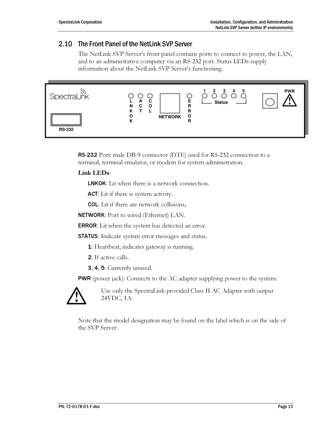
2.10 The Front Panel of the NetLink SVP Server
The NetLink SVP Server’s front panel contains ports to connect to power, the LAN, and to an administrative computer via an
|
|
|
|
|
|
|
|
|
|
|
L |
| A |
| C |
|
|
|
|
| E |
N |
| C |
| O |
|
|
|
|
| R |
K |
| T |
| L |
|
|
|
|
| R |
O |
|
|
|
|
| NETWORK |
| O | ||
K |
|
|
|
|
|
|
|
|
| R |
1 |
| 2 |
| 3 |
| 4 |
| 5 |
| PWR |
Status
Link LEDs:
LNKOK: Lit when there is a network connection.
ACT: Lit if there is system activity.
COL: Lit if there are network collisions. NETWORK: Port to wired (Ethernet) LAN. ERROR: Lit when the system has detected an error. STATUS: Indicate system error messages and status.
1: Heartbeat, indicates gateway is running.
2: If active calls.
3, 4, 5: Currently unused.
PWR (power jack): Connects to the AC adapter supplying power to the system.
Use only the
Note that the model designation may be found on the label which is on the side of the SVP Server.
PN: | Page 13 |