LC24-30 specifications
The Star Micronics LC24-30 is a high-performance dot matrix printer designed to meet the needs of various business environments. This versatile printer stands out for its reliability and efficiency, ideal for printing invoices, receipts, and reports in retail, logistics, and hospitality settings. Its robust construction ensures longevity and dependability even in demanding conditions, making it a preferred choice for businesses looking for a reliable printing solution.One of the standout features of the LC24-30 is its exceptional printing speed. With a maximum speed of 550 characters per second, it minimizes wait times and enhances productivity, ensuring that users can efficiently manage their operations. Additionally, this printer supports multi-part forms, allowing it to print on up to five layers simultaneously, which is crucial for applications requiring multiple copies of a document.
The LC24-30 employs advanced technology to deliver high-quality output. It features a 24-pin print head, which produces clear, crisp text and graphics, making it suitable for various applications, from standard invoices to detailed packing slips. The printer's resolution ensures that even small font sizes remain legible, while its ability to print barcodes adds versatility to its functionality.
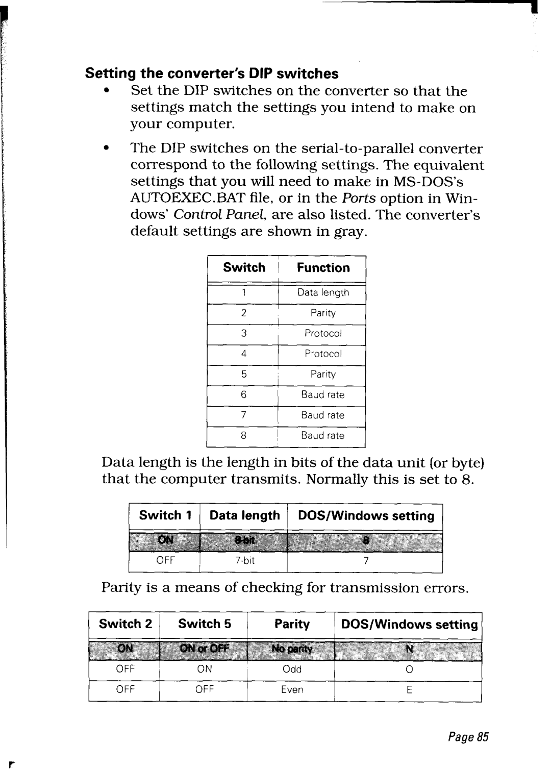
Connectivity is another significant advantage of the Star Micronics LC24-30. It supports LAN, USB, and parallel interfaces, making it easy to integrate into various systems and workflows. This adaptability ensures that businesses can utilize the printer alongside existing equipment without significant modifications, simplifying installation and setup.
Moreover, the LC24-30 features an easy-to-load paper mechanism, enabling users to quickly replenish paper supplies without disrupting operations. The printer's durable design is complemented by its energy-efficient operation, making it an eco-friendly choice for businesses aiming to reduce their carbon footprint.
In summary, the Star Micronics LC24-30 is a reliable dot matrix printer equipped with advanced features and technologies to enhance productivity and efficiency in various business environments. With its high-speed printing, high-quality output, and versatile connectivity options, the LC24-30 proves to be a worthy investment for organizations looking to streamline their printing processes while maintaining the highest standards of quality. Its robust construction and user-friendly design make it an ideal choice for both small and large enterprises alike.

