Manuals
/
Star Micronics
/
Computer Equipment
/
Printer
Star Micronics
SP200F
user manual
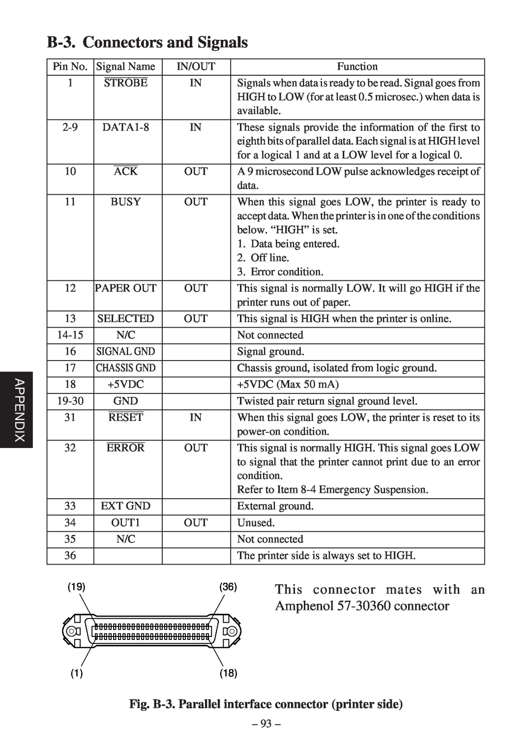
B-3. Connectors and Signals, This connector mates with an
Models:
SP200F
1
96
111
111
Download
111 pages
49 Kb
93
94
95
96
97
98
99
100
Specification
Install
Connecting the cable
Dimension
Maintenance
Panneau de Commande
A-1. Connectors and Signals
How to
A-3. Dip Switch Setting
Page 96
Image 96
Page 95
Page 97
Page 96
Image 96
Page 95
Page 97
Contents
SP200F SERIES
DOT MATRIX PRINTER
USER’S MANUAL MODE D’EMPLOI
BEDIENUNGSANLEITUNG MANUALE DI ISTRUZIONI
Federal Communications Commission Radio Frequency Interference
Statement
Statement of The Canadian Department of Communications
Radio Interference Regulations
TABLE OF CONTENTS
1. Outline
2. Unpacking and Installation
2-1. Unpacking
SP210 type
SP240 type
2-4. Maintenance
2-2. Locating the printer
2-3. Handling Care
3. Parts Identification and Nomenclature
Fig. 3-1 External view of the printer SP210 type
Fig. 3-2 External view of the printer SP240 type
4. Loading the Ribbon Cartridge and Paper
4-1. SP210 type
4-1-1. Loading the Ribbon Cartridge
4-1-2. Loading the Paper
Fig. 4-4 Removing the cover
3 Confirm that the power of the printer is turned on
2 Cut off the front edge of the roll paper perpendicularly
Release the paper roll holder to se- cure the paper
corrected
4-2. SP240 type
4-2-1. Loading the Ribbon Cartridge
4 Place the ribbon cartridge in the
4-2-2. Loading the Paper
Fig. 4-12 Removing the cover
Fig. 4-13 Loading the paper
8 Insert the tip of the roll paper in the auto cutter paper slit
When using copying paper
9 Pull on the edge of the paper to
remove any slack and then lower the auto cutter
Fig. 4-16 Insertion of the paper into the auto cutter
4-4. Connecting the Interface Cable
4-4-1. Ferrite core installation EU only
4-3. Removing the Paper
4-4-2. Serial Interface Cable
4-4-3. Parallel Interface Cable
Fig. 4-20 Connecting the interface cable
Fig. 4-21 Connecting the parallel interface cable
5. Control Panel
5-1. Basic Operation
5-2. Switch Operation Combined Switch Operation
2 Hexadecimal dump mode
STAR mode 6-1. Control Codes Used in Character Setting
6-2. Control Codes Used in Print Mode Setting
6. Control Codes
6-3. Control Codes Used in Line Spacing
6-4. Control Codes Used for Peripheral Units
6-5. Auto Cutter Control SP240 type only
6-6. Other Control Codes
Immediate drive command “B” for peripheral unit
ENGLISH
TABLE DES MATIERES
L’appendice n’est pas traduit
FRANÇAIS
1. Introduction
2. Déballage et Inspection
2-1. Déballage
Modèle SP210
Modèle SP240
2-2. Emplacement de l’imprimante
2-3. Précautions de manipulation
2-4. Entretien
3. Identification des Pièces et Nomenclature
Fig. 3-1 Vue externe de l’imprimante Modèle SP210
Fig. 3-2 Vue externe de l’imprimante Modèle SP240
4-1-1. Installation d’une cartouche à ruban
4-1. Modèle SP210
4. Installation d’une cartouche à ruban et chargement du papier
4-1-2. Chargement du papier
Fig. 4-4 Dépose du capot
Fig. 4-5 Chargement du papier
4-2-1. Installation d’une cartouche à ruban
4-2. Modèle SP240
6 Refermez l’unité de découpage automatique
4-2-2. Chargement du papier
Fig. 4-12 Dépose du capot
Fig. 4-13 Chargement du papier
de papier FEED
8 Insérez l’extrémité du papier dans
l’unité de découpage automatique
4-4-1. Installation du tore de ferrite UE seulement
4-3. Enlèvement d’un rouleau de papier
4-4. Connexion du câble d’interface
4-4-2. Câble d’interface série
4-4-3. Câble d’interface parallèle
Fig. 4-20 Connexion du câble d’inter
face série
5. Panneau de Commande
5-1. Fonctionnement de base
5-2. Utilisation des touches Utilisation combinée des touches
2 Vidage hexadécimal
Mode STAR 6-1. Commandes utilisées pour le réglage des caractères
6-3. Commandes utilisées pour l’espacement des lignes
6. Codes de contrôle
6-4. Commandes utilisées pour le pilotage des appareils périphériques
6-6. Autres commandes
FRANÇAIS
INHALTSVERZEICHNIS
Der Anhand dieser Bedienungsanleitung ist nur in englischer Sprache
DEUTSCH
1. Kurzbeschreibung
2. Auspacken und Aufstellen
2-1. Überprüfen
Typ SP210
Typ SP240
2-2. Wahl eines Aufstellungsorts für den Drucker
2-3. Hinweise zum Umgang
2-4. Wartung
3. Beschreibung und Bezeichnung der Geräteteile
Abb. 3-1 Außenansicht des Druckers Typ SP210
Abb. 3-2 Außenansicht des Druckers Typ SP240
Zum Anschluß des Druckers an den Hostcomputer
4. Einlegen von Farbbandkassette und Papier
4-1. Typ SP210
4-1-1. Einlegen der Farbbandkassette
4-1-2. Einlegen von Papier
Abb. 4-4 Entfernen der Abdeckung
Abb. 4-5 Papier einlegen
3 Bestätigen Sie, daß der Drucker einge schaltet ist
automatisch aus dem Papierauslaufschlitz
übereinstimmen
4-2. Typ SP240
4-2-1. Einlegen der Farbbandkassette
Abb. 4-8 Abdeckung abnehmen
Abb. 4-9 Anheben des Schneidwerks
6 Das Schneidwerk schließen
4-2-2. Einlegen von Papier
Abb. 4-12 Entfernen der Abdeckung
Abb. 4-13 Einlegen des Papiers
8 Führen Sie die Oberkante des Pa
9 Ziehen Sie die Kante des Papiers
4-3. Entfernen des Rollenpapiers
4-4. Anschließen des Schnittstellenkabels
4-4-1. Anbringen des Ferritkerns nur EU
4-4-2. Serielles Schnittstellenkabel
4-4-3. Paralleles Schnittstellenkabel
5. Bedienfeld
5-1. Grundlegender Betrieb
5-2. Tastenbedienung kombinierte Tastenbedienung
2 Sedezimale Datenausgabe
6. Steuercodes
STAR-Modus 6-1. Steuercodes für Zeicheneinstellung
6-2. Steuercodes für Druckmoduseinstellung
6-3. Steuercodes für Zeilenabstand
6-4. Steuercodes für Peripheriegeräte
6-5. Steuerung für Schneidwerk nur Typ SP240
6-6. Andere Steuercodes
Treiberimpuls-Einstellung für Peripheriegerät Vor
DEUTSCH
INDICE
L’Appendice appare solo nella sezione in inglese di questo manuale
ITALIANO
1. Descrizione
2. Disimballaggio e installazione
2-1. Disimballaggio
Tipo SP210
Tipo SP240
2-2. Collocazione della stampante
2-3. Precauzioni per l’uso
2-4. Manutenzione
3. Identificazione delle parti e nomenclatura
Fig. 3-1 Vista esterna della stampante tipo SP210
Fig. 3-1 Vista esterna della stampante tipo SP240
4-1. Tipo SP210
4-1-1. Inserimento della cartuccia nastro
4. Inserimento della cartuccia nastro e della carta
4-1-2. Inserimento della carta
Fig. 4-4 Rimozione del coperchio
3 Verificare che la stampante sia accesa
4-2. Tipo SP240
4-2-1. Inserimento della cartuccia nastro
6 Chiudere la taglierina automati- ca
4-2-2. Inserimento della carta
Fig. 4-12 Rimozione del coperchio
Fig. 4-13 Inserimento della carta
8 Inserire l’estremità superiore della
9 Tirare il bordo del carta per elimina
re eventuali allentamenti e quindi abbassare la taglierina automatica
Fig. 4-16 Inserimento della carta nella taglierina automatica
quando si usa carta autocopiante
4-4-1. Installazione dell’anello di ferrite solo UE
4-3. Rimozione della carta
4-4. Collegamento del cavo interfaccia
4-4-2. Cavo interfaccia seriale
4-4-3. Cavo interfaccia parallelo
Fig. 4-20 Collegamento del cavo interfaccia
Fig. 4-21 Collegamento del cavo interfaccia parallelo
5. Pannello comandi
5-1. Funzionamento basilare
1 STAMPA AUTOMATICA
2 Modo di scaricamento esadecimale
6. Codici di controllo
Modo STAR
6-1. Codici di controllo usati nell’impostazione dei caratteri
6-2. Codici di controllo usati nell’impostazione del modo di stampa
6-4. Codici di controllo usati per unità periferiche
6-5. Controllo della taglierina automatica solo tipo SP240
6-6. Altri codici di controllo
A-1. Connectors and Signals
Appendix A Serial Interface
RS-232C
Fig. A-1 Serial interface connector
A-2. Interface Connections
Fig. A-2 Example of interface connections
APPENDIX
A-3. Dip Switch Setting
DIP-SW
International character set
A-4. Communication Protcol
Data transmission rate baud rate
Paper out
B-1. Interface Specifications
Appendix B Parallel Interface
B-2. Interface Timing
B-3. Connectors and Signals
This connector mates with an
Amphenol 57-30360 connector
Fig. B-3. Parallel interface connector printer side
B-4. Dip Switch Setting
Character generation
Fig. B-4 DIP switch array
Appendix C Peripheral Unit Drive Circuit
Use cables which meet the following specifications
Note Pin 1 must be shield drain wire connected to
1 Connecting the cable
2 Drive circuit
Fig. C-3 Drive circuit
drawer
Appendix D General Specifications
Note The paper must not be glued to the core
Paper cutter reliability
SP210 Type
SP240 Type
Fig. D-1 Overall dimensions mm
158 234 193
Appendix E Character Font Table
E-1. U.S.A
APPENDIX
E-2. Europe
APPENDIX
E-3. International Character Sets
E-4. VeriFont
APPENDIX
Page
OVERSEAS SUBSIDIARY COMPANIES
STAR MICRONICS AMERICA, INC
ELECTRONIC PRODUCTS DIVISION
1150 King Georges Post Road, Edison, NJ 08837-3729 U.S.A
Top
Page
Image
Contents