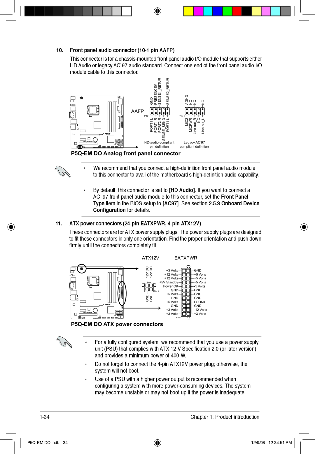
10.Front panel audio connector (10-1 pin AAFP)
This connector is for a
![]()
GND PRESENCE# SENSE1 RETUR | SENSE2 RETUR | |||||||
AAFP |
|
|
|
|
|
|
|
|
|
|
|
|
| ||||
PIN 1 |
|
|
|
|
|
|
|
|
PORT1 L PORT1 R PORT2 R SENSE SEND PORT1 L | ||||||||
pin definition
AGND NC NC | NC |
PIN 1
Line out_L
NC
Line out_R
MICPWR
MIC2
Legacy AC’97
compliant definition
P5Q-EM DO Analog front panel connector
•We recommend that you connect a
•By default, this connector is set to [HD Audio]. If you want to connect a AC’ 97 front panel audio module to this connector, set the Front Panel Type item in the BIOS setup to [AC97]. See section 2.5.3 Onboard Device
Configuration for details.
11.ATX power connectors
These connectors are for ATX power supply plugs. The power supply plugs are designed to fit these connectors in only one orientation. Find the proper orientation and push down firmly until the connectors completely fit.
ATX12V |
| EATXPWR | ||
DC DC | +3 Volts | GND | ||
+12V +12V | ||||
+12 | Volts | +5 Volts | ||
+12 | Volts | +5 Volts | ||
| +5V Standby | +5 Volts | ||
| Power OK | |||
PIN 1 |
| GND | GND | |
GND GND | +5 Volts | GND | ||
| GND | GND | ||
+5 Volts | PSON# | |||
| ||||
|
| GND | GND | |
| +3 | Volts | ||
+3 | Volts | +3 Volts | ||
| ||||
|
| PIN 1 |
| |
P5Q-EM DO ATX power connectors
•For a fully configured system, we recommend that you use a power supply unit (PSU) that complies with ATX 12 V Specification 2.0 (or later version) and provides a minimum power of 400 W.
•Do not forget to connect the
•Use of a PSU with a higher power output is recommended when configuring a system with more
Chapter 1: Product introduction |
12/9/08 12:34:51 PM