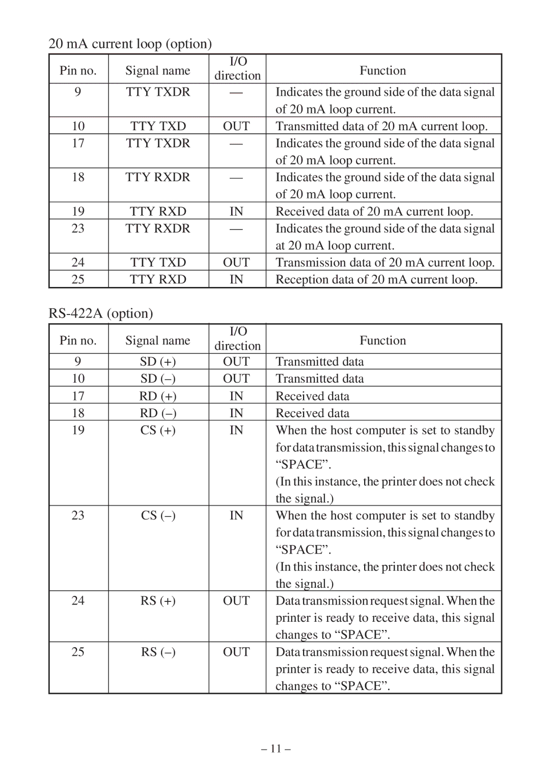
20 mA current loop (option)
Pin no. | Signal name | I/O | Function | |
direction | ||||
|
|
| ||
9 | TTY TXDR | — | Indicates the ground side of the data signal | |
|
|
| of 20 mA loop current. | |
10 | TTY TXD | OUT | Transmitted data of 20 mA current loop. | |
17 | TTY TXDR | — | Indicates the ground side of the data signal | |
|
|
| of 20 mA loop current. | |
18 | TTY RXDR | — | Indicates the ground side of the data signal | |
|
|
| of 20 mA loop current. | |
19 | TTY RXD | IN | Received data of 20 mA current loop. | |
23 | TTY RXDR | — | Indicates the ground side of the data signal | |
|
|
| at 20 mA loop current. | |
24 | TTY TXD | OUT | Transmission data of 20 mA current loop. | |
25 | TTY RXD | IN | Reception data of 20 mA current loop. |
RS-422A (option)
Pin no. | Signal name | I/O | Function | |
direction | ||||
|
|
| ||
9 | SD (+) | OUT | Transmitted data | |
10 | SD | OUT | Transmitted data | |
17 | RD (+) | IN | Received data | |
18 | RD | IN | Received data | |
19 | CS (+) | IN | When the host computer is set to standby | |
|
|
| for data transmission, this signal changes to | |
|
|
| “SPACE”. | |
|
|
| (In this instance, the printer does not check | |
|
|
| the signal.) | |
23 | CS | IN | When the host computer is set to standby | |
|
|
| for data transmission, this signal changes to | |
|
|
| “SPACE”. | |
|
|
| (In this instance, the printer does not check | |
|
|
| the signal.) | |
24 | RS (+) | OUT | Data transmission request signal. When the | |
|
|
| printer is ready to receive data, this signal | |
|
|
| changes to “SPACE”. | |
25 | RS | OUT | Data transmission request signal. When the | |
|
|
| printer is ready to receive data, this signal | |
|
|
| changes to “SPACE”. |
– 11 –
