2-6-3. STX-ETX mode
This mode is accessed from whichever DTR mode or
The host computer sends an ENQ code to the printer and acknowledges the printer status. Then, the host computer checks if the printer buffer is empty. After the host computer detects that the buffer is empty, a STX code and data are transmitted. After 1 block of data is transmitted, the host computer sends an ENQ code to the printer and then receives the printer status and check byte (horizontal parity for the printer.)
At this points, the host computer performs a status and horizontal parity check. When the host computer determines that there was no error, it transmits an ETX code which serves as text end code. After the printer receives the ETX code, data in the data buffer is printed out. If an error occurs, a CAN code is transmitted by the host computer. (In this instance, the data which was previously sent to the buffer is cleared, thus, the host computer must retransmit the same data to the printer.)
A flowchart of this operation is illustrated on the following page.
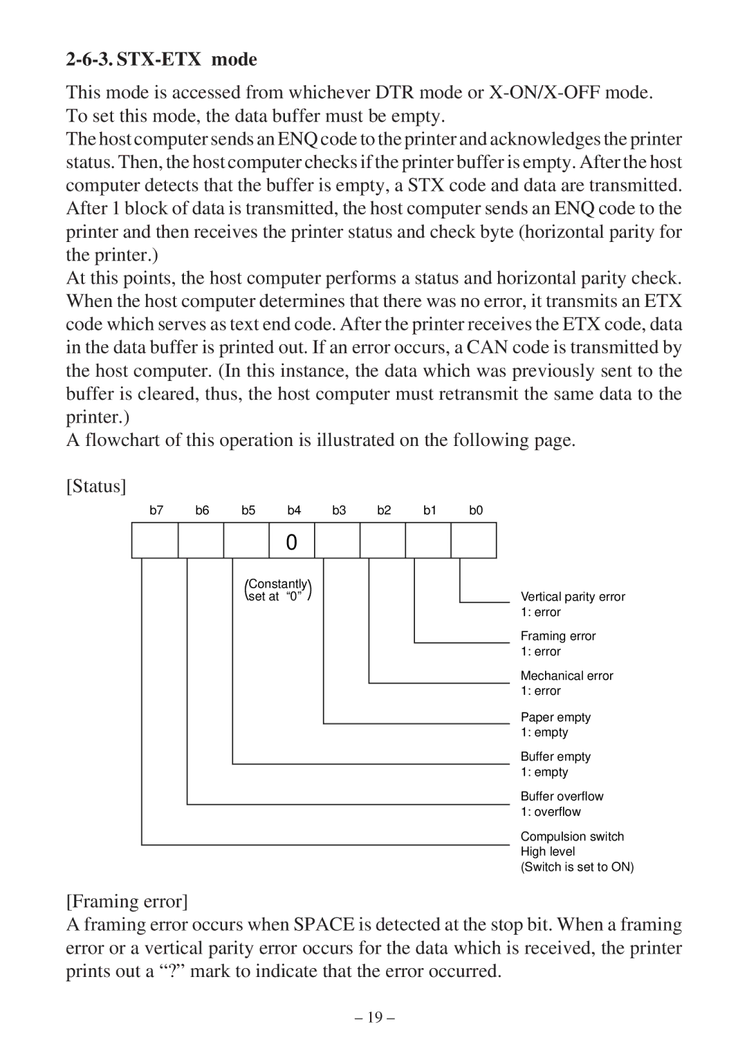
[Status]
b7 | b6 | b5 | b4 | b3 | b2 | b1 | b0 |
0
Constantly set at “0”
Vertical parity error 1: error
Framing error 1: error
Mechanical error 1: error
Paper empty 1: empty
Buffer empty 1: empty
Buffer overflow 1: overflow
Compulsion switch High level
(Switch is set to ON)
[Framing error]
A framing error occurs when SPACE is detected at the stop bit. When a framing error or a vertical parity error occurs for the data which is received, the printer prints out a “?” mark to indicate that the error occurred.
– 19 –