PLANNING THE VENT SYSTEM
Plan the route of the vent system from the exhaust elbow to the planned location of the vent terminal.
1.Layout total vent system to use a minimum of vent pipe and elbows.
2.This water heater is capable of venting flue gases equivalent to 25’ (7.6 m) of 2” pipe, 65’ (19.8 m) of 3” pipe, or 128’ (39.0 m) of 4” pipe as listed in Table 1.
TABLE 1
Number of | 2” Maximum | 3” Maximum | 4” Maximum |
90° Elbows | Pipe - ft. (m) | Pipe - ft. (m) | Pipe - ft. (m) |
1 | 20 | (6.1) | 60 (18.3) | 120 (36.6) |
2 | 15 | (4.6) | 55 (16.8) | 112 (34.1) |
3 | 10 | (3.0) | 50 (15.2) | 104 (31.7) |
4 | | -- | 45 (13.7) | 96 (29.3) |
5 | | -- | 40 (12.2) | 88 (26.8) |
6 | | -- | 35 (10.7) | 80 (24.3) |
The minimum vent lengths for each of the pipe sizes is one 90° plus 2’ (61 cm) of straight pipe and the appropriate termination.
NOTE: The equivalent feet (m) of pipe listed above are exclusive of the termination. That is, the termination, with an installed screen, is assumed to be in the system and the remainder of the system must not exceed the lengths discussed above.
3.The exhaust elbow assembly is designed to accept only straight sections of 2” pipe. To start, a minimum of 2” (5.1cm) of 2” pipe must be inserted and glued to the exhaust elbow assembly if utilizing 3” or 4” vent pipe. Use the same method with the blower inlet if a direct vent configuration is utilized.
If using 2” inch vent pipe:
A minimum of 2” (5.1cm) diameter vent pipe must be attached to the exhaust elbow assembly. The total system cannot exceed the lengths discussed above, where each elbow is equal to 5 equivalent feet (1.5m) of straight pipe.
If using 3” or 4” inch vent pipe:
Two inches (5.1cm) of 2” pipe must be attached to the exhaust elbow assembly before adding a reducer to acquire the desired pipe diameter. An appropriately sized 45 degree elbow (supplied locally-a schedule 40 DWV) vent terminal must be obtained with an equivalent screen (supplied in vent kit). The total system cannot exceed the equivalent pipe lengths discussed above where each elbow is equal to 5 feet (1.5m) of straight pipe (3” vent pipe) or 8 feet (2.4m) of straight pipe (4” vent pipe).
U.S. INSTALLATIONS:
NOTE: This unit can be vented with PVC pipe materials (Cellular Core ASTM-F891; DWV ASTM-D2665 or CSA B181.2; Schedule 40, 80, 120 ASTM-D1785 or CSA B137.3; or SDR Series ASTM-D2241 or CSA B137.3), CPVC pipe materials (CPVC41 ASTM-D2846 or CSA B137.6; Schedule 40, 80 ASTM-F441 or CSA B137.6; or SDR Series ASTM-F442), ABS pipe materials (Schedule 40 DWV ASTM-D2661 or CSAB181.1 or Schedule 40 DWV Cellular CoreASTM-F628). The fittings, other than the TERMINATION should be equivalent to PVC-
DWV fittings meetingASTM D-2665 (Use CPVC fittings, ASTM F-438 for CPVC pipe and ABS fittings, ASTM D-2661/3311 for ABS pipe). If CPVC or ABS pipe and fittings are used, then proper cement must be used for all joints, including joining the pipe to Termination (PVC Material). If local codes do not allow the use of the PVC termination when a material other than PVC is used for venting, then an equivalent fitting of that material may be substituted if the screen in the PVC terminal is removed and inserted into the new fitting.
Canadian Installation of this water heater must comply with CAN/
CSA B149.1 - Natural Gas and Propane Installation Code which requires the vent system components be certified to ULC S636.
This water heater has been design certified to be vented with PVC pipe certified and marked as complying with ULC S636. This water heater is supplied with a 2 inch 22.5 degree termination elbow that is a special fitting that must be used with the appliance. Any outlet piping, fittings and glue used to vent this appliance that is not supplied by the manufacturer must comply with the ULC S636 requirements.
PVC Materials should use ASTM D-2564 Grade Cement; CPVC
Materials should use ASTM F-493 Grade Cement and ABS Materials should use ASTM D-2235 Grade Cement.
If the water heater is being installed as a replacement for an existing power vented heater in pre-existing venting, a thorough inspection
of existing venting system must be performed prior to any installation work. Verify that correct material as detailed above has been used, and that the minimum or maximum vent lengths and terminal location as detailed in this manual have been met. Carefully inspect the entire venting system for any signs of cracks or fractures, particularly at joints between elbows and other fittings and straight runs of vent pipe. Check system for signs of sagging or other stresses in joints as a result of misalignment of any components in the system. If any of these conditions are found, they must be corrected in accordance with the venting instructions in this manual before completing installation and putting the water heater into service.
NOTE: A. For water heaters in locations with high ambient temperatures (above 100°F) it is recommended that CPVC or ABS pipe and fittings be used. B. A 22.5 degree elbow (2” vent pipe) or a 45 degree elbow (3” and 4” vent pipe) with an installed
screen VENT TERMINAL must be used in all cases.
4.There will be some installations where condensate will be formed in the horizontal runs of the vent system. This condensate will run into the condensate elbow. The water heater is shipped with a condensate hose that attaches to the condensate elbow. No other tee or fitting is required.
CONDENSATE
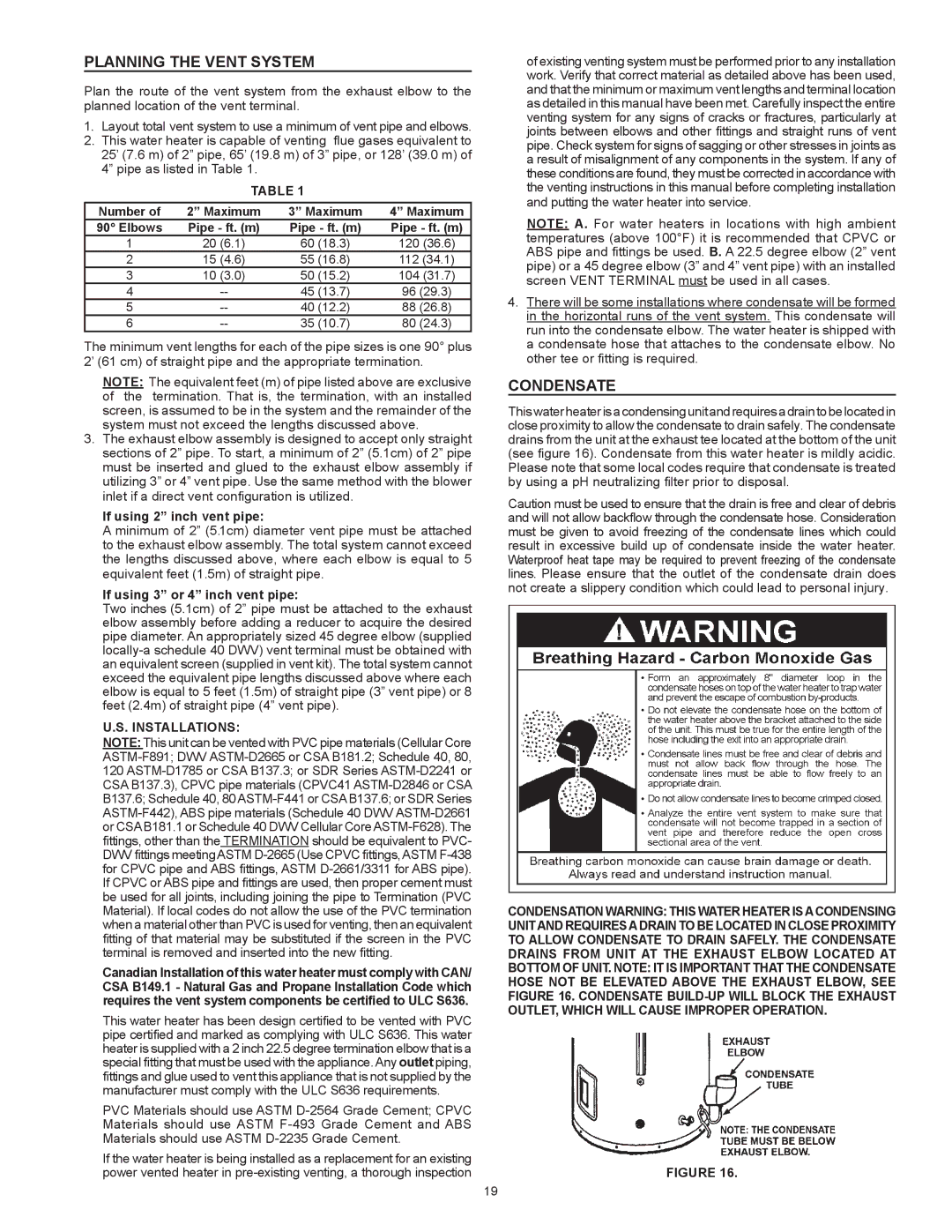
Thiswaterheaterisacondensingunitandrequiresadraintobelocatedin close proximity to allow the condensate to drain safely. The condensate drains from the unit at the exhaust tee located at the bottom of the unit (see figure 16). Condensate from this water heater is mildly acidic. Please note that some local codes require that condensate is treated by using a pH neutralizing filter prior to disposal.
Caution must be used to ensure that the drain is free and clear of debris and will not allow backflow through the condensate hose. Consideration must be given to avoid freezing of the condensate lines which could result in excessive build up of condensate inside the water heater. Waterproof heat tape may be required to prevent freezing of the condensate lines. Please ensure that the outlet of the condensate drain does not create a slippery condition which could lead to personal injury.
CONDENSATION WARNING: THIS WATER HEATER ISACONDENSING UNITAND REQUIRESADRAIN TO BE LOCATED IN CLOSE PROXIMITY TO ALLOW CONDENSATE TO DRAIN SAFELY. THE CONDENSATE DRAINS FROM UNIT AT THE EXHAUST ELBOW LOCATED AT BOTTOM OF UNIT. NOTE: IT IS IMPORTANT THAT THE CONDENSATE HOSE NOT BE ELEVATED ABOVE THE EXHAUST ELBOW, SEE FIGURE 16. CONDENSATE BUILD-UP WILL BLOCK THE EXHAUST OUTLET, WHICH WILL CAUSE IMPROPER OPERATION.
FIGURE 16.