CONTROLS AND SWITCHES

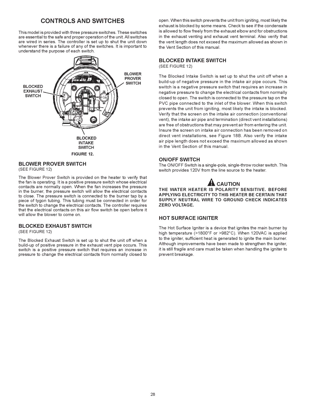
This model is provided with three pressure switches. These switches are essential to the safe and proper operation of the unit. All switches are wired in series. The controller is set up to shut the unit down whenever there is a failure of any of the switches. It is important to understand the purpose of each switch.

FIGURE 12.

BLOWER PROVER SWITCH

(SEE FIGURE 12)

The Blower Prover Switch is provided on the heater to verify that the fan is operating. It is a positive pressure switch whose electrical contacts are normally open. When the fan increases the pressure in the burner, the pressure switch will allow the electrical contacts to close. The pressure switch is connected to the burner tap by a piece of tygon tubing. This tubing must be connected in order for the switch to change the electrical contacts. The controller requires that the electrical contacts on this air flow switch be open before it will allow the blower to come on.

BLOCKED EXHAUST SWITCH

(SEE FIGURE 12)

The Blocked Exhaust Switch is set up to shut the unit off when a build-up of positive pressure in the exhaust vent pipe occurs. This switch is a positive pressure switch that requires an increase in pressure to change the electrical contacts from normally closed to

open. When this switch prevents the unit from igniting, most likely the exhaust is blocked by some means. Check to see if the condensate is allowed to flow freely from the exhaust elbow and for obstructions in the exhaust venting and exhaust vent terminal. Also verify that the vent length does not exceed the maximum allowed as shown in the Vent Section of this manual.

BLOCKED INTAKE SWITCH

(SEE FIGURE 12)

The Blocked Intake Switch is set up to shut the unit off when a build-up of negative pressure in the intake air pipe occurs. This switch is a negative pressure switch that requires an increase in negative pressure to change the electrical contacts from normally closed to open. The switch is connected to the pressure tap on the PVC pipe connected to the inlet of the blower. When this switch prevents the unit from igniting, most likely the intake is blocked. Verify that the screen on the intake air connection (conventional vent), the intake air pipe and termination (direct vent installations) are free of obstructions that may prevent air from entering the unit. Insure the screen on intake air connection has been removed on direct vent installations, see Figure 18B. Also verify the intake air pipe length does not exceed the maximum allowed as shown in the Vent Section of this manual.

ON/OFF SWITCH

The ON/OFF Switch is a single-pole, single-throw rocker switch. This switch provides 120V from the line source to the heater.

CAUTION

THE WATER HEATER IS POLARITY SENSITIVE. BEFORE APPLYING ELECTRICITY TO THIS HEATER BE CERTAIN THAT SUPPLY NEUTRAL WIRE TO GROUND CHECK INDICATES ZERO VOLTAGE.

HOT SURFACE IGNITER

The Hot Surface Igniter is a device that ignites the main burner by high temperature (>1800°F or >982°C). When 120VAC is applied to the igniter, sufficient heat is generated to ignite the main burner. Although improvements have been made to strengthen the igniter, it is still fragile and care must be taken when handling the igniter to prevent breakage.

28

Page 28
Image 28
State Industries A B C D E F 100 Blower Prover Switch, Blocked Exhaust Switch, Blocked Intake Switch, ON/OFF Switch

A B C D E F 100 specifications

State Industries A B C D E F 100 is a groundbreaking initiative aimed at revolutionizing various sectors including manufacturing, technology, and services, by integrating advanced methodologies and innovative practices. This initiative underscores a commitment to sustainability, efficiency, and quality, setting new standards for industry performance.

One notable feature of State Industries A B C D E F 100 is its focus on automation and smart manufacturing technologies. This includes the implementation of the Internet of Things (IoT) devices that facilitate real-time data collection and analysis. By harnessing this data, industries can optimize their operations, leading to improved productivity and reduced operational costs. Machine learning algorithms play a crucial role in predictive maintenance, enabling timely interventions that minimize downtime and enhance equipment longevity.

Another key aspect of State Industries A B C D E F 100 is the emphasis on renewable energy solutions. Many facilities are transitioning towards solar, wind, and other sustainable energy sources, which not only lowers carbon footprints but also leads to considerable savings in energy costs. This shift towards clean energy reflects a broader commitment to corporate social responsibility, addressing the environmental challenges faced by today’s industries.

Moreover, the initiative promotes the use of advanced materials and smart technologies in product development. These innovations not only enhance product functionality but also improve safety and sustainability. For instance, the use of biodegradable materials in packaging aligns with global efforts to reduce plastic waste, while advancements in nanotechnology offer unique solutions to traditional manufacturing challenges.

Collaboration stands as another essential characteristic of State Industries A B C D E F 100. By fostering partnerships between different stakeholders, including academia, government agencies, and private enterprises, the initiative encourages knowledge sharing and co-creation of solutions. This collaborative approach leads to the development of best practices that can be shared across sectors, amplifying the impact of technological advancements.

In conclusion, State Industries A B C D E F 100 embodies the future of industrial evolution, integrating cutting-edge technologies, sustainable practices, and collaborative efforts to create a resilient and forward-thinking industrial landscape. As industries continue to adapt to the changing global environment, the principles established by this initiative will likely play a pivotal role in shaping a sustainable and prosperous future for all.