2 |
PRIMARY UNIT
|
|
|
|
|
|
|
|
|
|
|
|
|
|
| P | C | B | R | G |
|
|
|
|
|
|
|
| S | P | T | C | B |
|
|
|
|
|
|
|
|
| U | M | M | C |
|
|
|
|
|
|
|
|
|
|
|
| 31 |
|
|
|
|
|
|
|
|
|
|
|
|
|
|
|
|
|
|
|
|
|
|
|
|
|
|
|
|
|
|
|
|
Redundancy Communications Link
Redundancy Communications Link
CPU 780
|
|
|
| SECONDARY UNIT | a47002 | ||||||||
|
|
|
|
|
|
|
|
|
|
|
|
|
|
|
| P | C | B | R | G |
|
|
|
|
|
|
|
|
| S | P | T | C | B |
|
|
|
|
|
|
|
|
|
| U | M | M | C |
|
|
|
|
|
|
|
|
|
|
|
|
| 30 |
|
|
|
|
|
|
|
|
|
|
|
|
|
|
|
|
|
|
|
|
|
|
|
|
|
|
|
|
|
|
|
|
|
|
|
Genius Bus
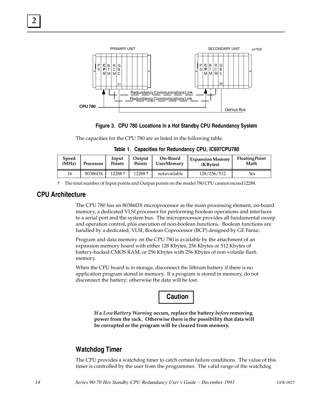
Figure 3. CPU 780 Locations in a Hot Standby CPU Redundancy System
The capacities for the CPU 780 are as listed in the following table.
Table 1. Capacities for Redundancy CPU, IC697CPU780
Speed |
| Input | Output | Expansion Memory | Floating Point | |
(MHz) | Processor | Points | Points | UserMemory | (KBytes) | Math |
|
|
|
|
|
|
|
|
|
|
|
|
|
|
16 | 80386DX | 12288 [ | 12288 [ | notavailable | 128/256/512 | Yes |
|
|
|
|
|
|
|
[The total number of Input points and Output points on the model 780 CPU cannot exceed12288.
CPU Architecture
The CPU 780 has an 80386DX microprocessor as the main processing element,
Program and data memory on the CPU 780 is available by the attachment of an expansion memory board with either 128 Kbytes, 256 Kbytes or 512 Kbytes of
When the CPU board is in storage, disconnect the lithium battery if there is no application program stored in memory. If a program is stored in memory, do not disconnect the battery; otherwise the data will be lost.
Caution
If a LowBattery Warning occurs, replace the battery beforeremoving power from the rack. Otherwise there is the possibility that data will be corrupted or the program will be cleared from memory.
Watchdog Timer
The CPU provides a watchdog timer to catch certain failure conditions. The value of this timer is controlled by the user from the programmer. The valid range of the watchdog
14 | Series |
|