4 |
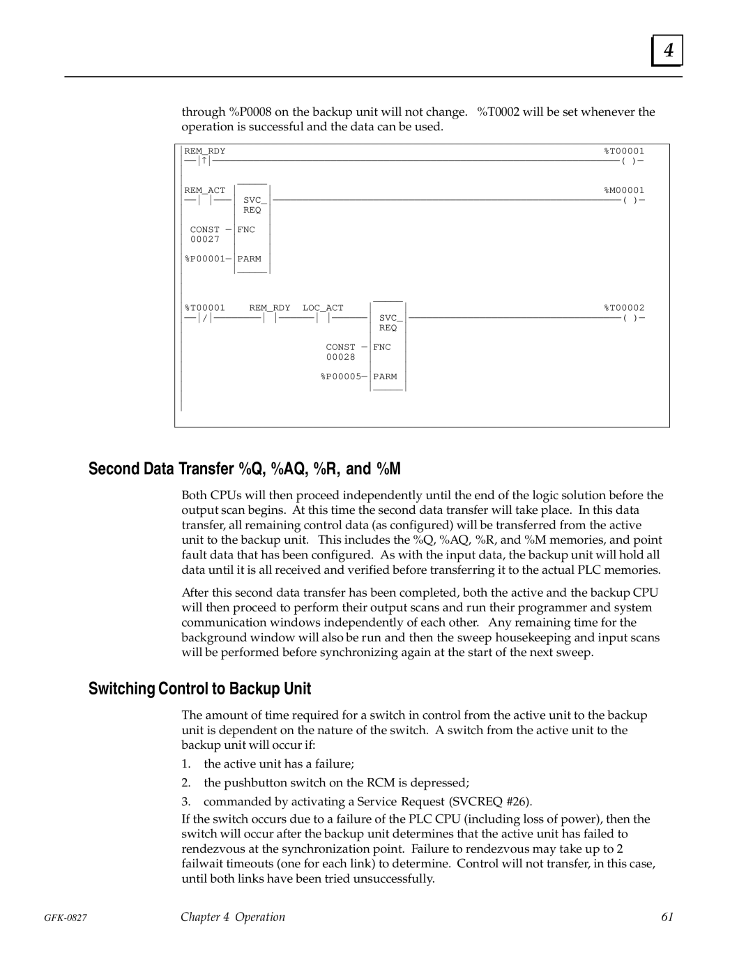
through %P0008 on the backup unit will not change. %T0002 will be set whenever the operation is successful and the data can be used.
REM_RDY | %T00001 |
ÐÐ↑ÐÐÐÐÐÐÐÐÐÐÐÐÐÐÐÐÐÐÐÐÐÐÐÐÐÐÐÐÐÐÐÐÐÐÐÐÐÐÐÐÐÐÐÐÐÐÐÐÐÐÈÐÐÐÐÐÐÐÐÐÐÐÐÐÐÐÐÐÐÐ( )Ð
|
|
|
|
| |
_____ |
|
|
|
| |
REM_ACT |
|
| %M00001 | ||
ÐÐ ÐÐÐ SVC_ÐÐÐÐÐÐÐÐÐÐÐÐÐÐÐÐÐÐÐÐÐÐÐÐÐÐÐÐÐÐÐÐÐÐÐÐÐÐÐÐÐÐÐÈÐÐÐÐÐÐÐÐÐÐÐÐÐÐÐÐ( )Ð | |||||
REQ |
|
|
| ||
|
|
| |||
CONST ÐFNC |
|
|
| ||
00027 |
|
|
| ||
|
|
| |||
%P00001ÐPARM |
|
|
| ||
_____ |
|
|
| ||
|
|
|
|
| |
|
|
|
|
| |
|
| _____ |
|
| |
%T00001 | REM_RDY LOC_ACT | %T00002 | |||
ÐÐ/ÐÐÐÐÐÐÐÐ ÐÐÐÐÐÐ ÐÐÐÐÐÐ SVC_ÐÐÐÐÐÐÐÐÐÐÐÐÐÐÐÐÐÐÐÐÐÐÐÐÈÐÐÐÐÐÐÐÐÐÐÐÐ( )Ð | |||||
|
| REQ |
| ||
|
|
| |||
| CONST ÐFNC |
| |||
| 00028 |
| |||
|
|
| |||
| %P00005ÐPARM |
| |||
|
| _____ |
| ||
|
|
|
|
| |
|
|
|
|
| |
Second Data Transfer %Q, %AQ, %R, and %M
Both CPUs will then proceed independently until the end of the logic solution before the output scan begins. At this time the second data transfer will take place. In this data transfer, all remaining control data (as configured) will be transferred from the active unit to the backup unit. This includes the %Q, %AQ, %R, and %M memories, and point fault data that has been configured. As with the input data, the backup unit will hold all data until it is all received and verified before transferring it to the actual PLC memories.
After this second data transfer has been completed, both the active and the backup CPU will then proceed to perform their output scans and run their programmer and system communication windows independently of each other. Any remaining time for the background window will also be run and then the sweep housekeeping and input scans will be performed before synchronizing again at the start of the next sweep.
Switching Control to Backup Unit
The amount of time required for a switch in control from the active unit to the backup unit is dependent on the nature of the switch. A switch from the active unit to the backup unit will occur if:
1.the active unit has a failure;
2.the pushbutton switch on the RCM is depressed;
3.commanded by activating a Service Request (SVCREQ #26).
If the switch occurs due to a failure of the PLC CPU (including loss of power), then the switch will occur after the backup unit determines that the active unit has failed to rendezvous at the synchronization point. Failure to rendezvous may take up to 2 failwait timeouts (one for each link) to determine. Control will not transfer, in this case, until both links have been tried unsuccessfully.
Chapter 4 Operation | 61 |