Electric Gasoline
Page
Table of Contents
Table of Contents
Page
Here’s how to get help
Parts Ordering Procedures
Stow Construction Equipment
Page
Page
Operator Instructional Data Sheet
Safety Precautions
Safety Precautions
Operation
Surface Grinder
MAINTENANCE, Repair and Storage
Safety Precautions
Removing the Surface Grinder from the Pallet
Assembly
Application All Models
Installing the SG24-1000 Safety and Dust Shield Assembly KIT
Filling the DFG/G Series Engine Fuel Tank
Before Starting the Engine
Filling the Engine Crankcase with OIL
Applications DFG/G Surface Grinder
Grinding Stones
MULTI-ACCESSORY Attachments and Applications
Operation
Theory of Operation
Scarifier Blocks
Tungsten Carbide Grinding Block
Star Flail
Cost 1 Productivity 3 Service Life
Beam Flail
Spacer Washer
Cost 1 Productivity 5 Service Life
Cost Productivity Service Life
Pentagonal Flail
Scarifier Block Bushing
Wire brushes
SCRAPE-R-TACH Industrial Floor Coatings Removal System
Floor Brushes
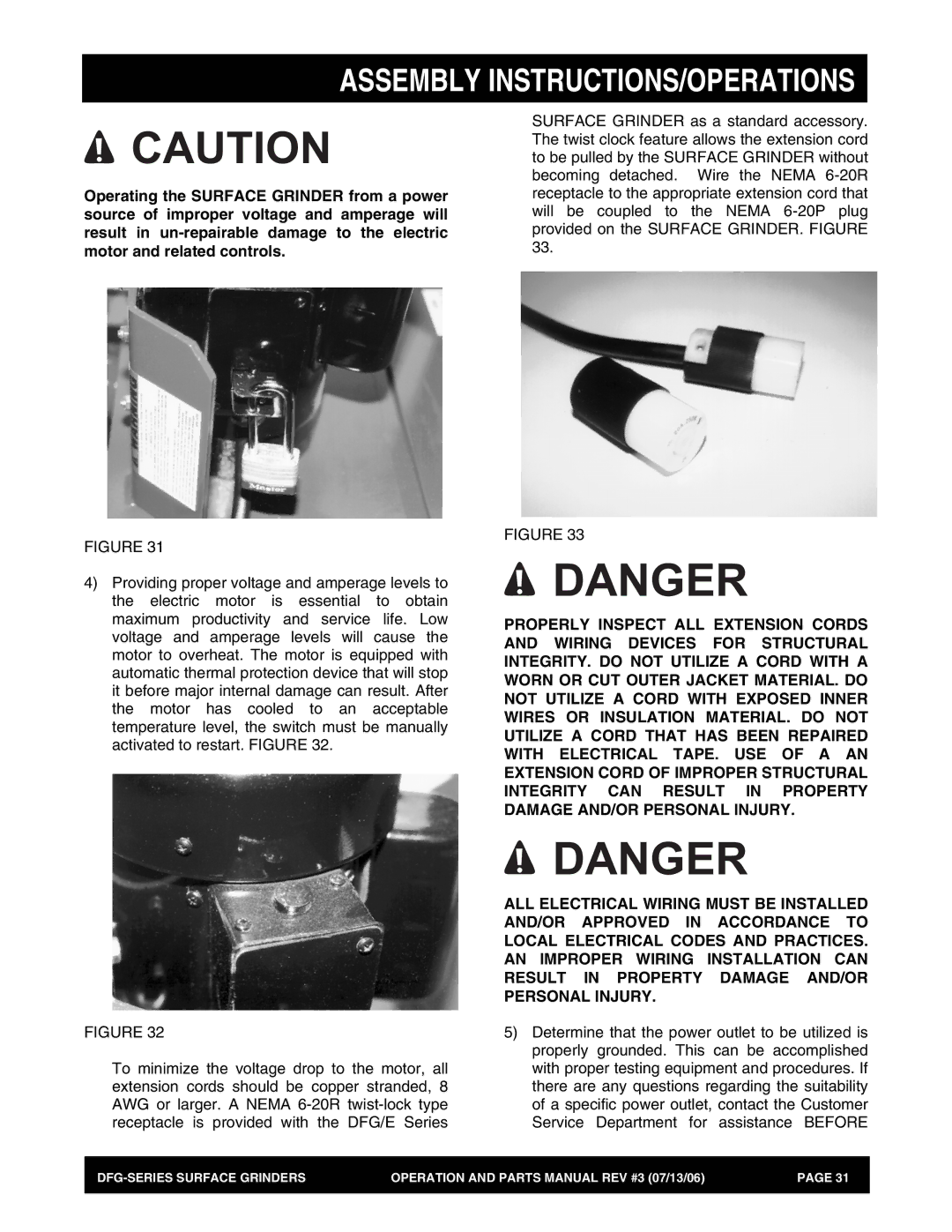
Assembly INSTRUCTIONS/OPERATIONS
Follow all safety precautions for the safety solvent
Diamond Segment Block
Assembly INSTRUCTIONS/OPERATIONS
From the Counterrotating Discs
Assembly INSTRUCTIONS/OPERATIONS
Adjusting the Operator Handle HEIGHT. Application All Models
Assembly INSTRUCTIONS/OPERATIONS
Assembly INSTRUCTIONS/OPERATIONS
Operating the Surface Grinder on the Jobsite
Fiure
Result in Property Damage AND/OR Personal Injury
Assembly INSTRUCTIONS/OPERATIONS
Application All Models Early Age Grinding
Stopping the DFG/G Series Gasoline Powered Surface Grinder
Definitions of floor flatness and levelness
Defined Versus Random Traffic Patterns
How to Define Surface Regularity
TR 34 tolerances for defined traffic floors
Assembly INSTRUCTIONS/OPERATIONS
Maintenance/Service
MAINTENANCE/SERVICE
Preventative Maintenance Check LIST. Application All Models
Observe all applicable safety precautions for the solvent
MAINTENANCE/SERVICE
Checking V-BELT Tension and Alignment
MAINTENANCE/SERVICE
Lubrication Requirements
Engine Service
Electric Motor Service
Troubleshooting
Troubleshooting
Accelerated Bearing Wear AND/OR Failure
Operational PROBLEMS. Application All Models
Uneven MULTI-ACCESSORY Attachment Wear
Accelerated V-BELT Wear
Storage
Storage
Typical Operator Handle Height
Specifications
Vacuum Cleaner Connection Diameter
Maximum Grinding Width
Page
Remarks
Part Name
Xxxxx only Not Used on
Units Gasoline Engine Units Electric Motor Model
Suggested Spare Parts
Qty Description
Operator Handle ASSY. Electric
Operator Handle ASSY. Electric
CABLE, Short
HANDLE, Operator Universal
HP Motor only
CABLE, Long
Operator Handle ASSY. Gasoline
Operator Handle ASSY. Gasoline
LEVER, Throttle CONTROL, W/CABLE & Knob
CABLE, Throttle
KNOB, Throttle Control
QTY Remarks
Electric Motor Assy
Electric Motor Assy
WASHER, Flat 5/16, Plated
MOUNT, Electric Motor
HP 50 HZ Motor
SCREW, CAP 5/16-18 UNC X 1 Plated
Gasoline Engine Assy
Gasoline Engine Assy
CAP, OIL Drain
ENGINE, Honda 11 H.P
MOUNT, Gasoline Engine
CLUTCH, Pulley Assy
Wheel Assy
Wheel Assy
WASHER, Flat ¾ Plated
ARM, Swing
Wheel
AXLE, Plated
Transmission Assy
Transmission Assy
WASHER, Lock 5/16 Plated
FRAME, Main
COVER, Transmission
BEARING, Flange
Head Assy
Head Assy
DISC, Mounting
DISC, MULTI- Accessory LH
DISC, MULTI- Accessory RH
BAR, Mounting
Safety and Dust Shield Assy
Safety and Dust Shield Assy
STRAP, Skirt
Skirt Assembly
SKIRT, Grinder
WASHER, Fender 1/4 , Plated
Scarifier Assy
Scarifier Assy
WEDGE, Plastic
Housing
Bushing
NUT, HEX 3/8 UNC, Nylock Plated
SCRAPE-R-TACH Assy
INSERT, Tungsten Carbide
HOLDER, Insert
MOUNT, Rubber
Spacer
Grinding Block Assy
General Purpose
Block
Ring
Aggress Grinding
Decals
Decals
DECAL, Throttle Sfdclsdp DECAL, Stow Large
Decals Part Name QTY Remarks
DECAL, Warning
DECAL, Operation
Freight Policy
Special Expediting Service
PRICING, Rebates Specifications
Payment Terms
Page
FAX
Heres HOW to GET Help