STUDER INNOTEC |
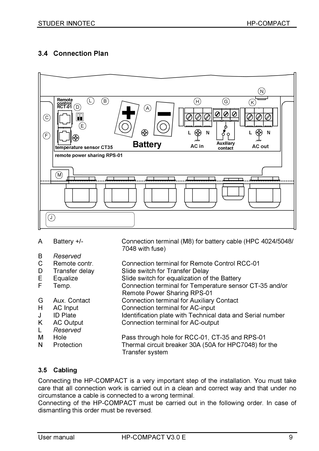
3.4 Connection Plan
Remote | L | B |
| H |
control |
| |||
D |
| A |
| |
C |
|
|
|
|
| E |
|
|
|
F |
|
| L | N |
|
|
|
|
|
|
| Battery |
|
|
|
|
|
| AC in | |||
temperature sensor CT35 | ||||||
remote power sharing |
|
|
|
| ||
G
Auxiliary
contact
| N |
K |
|
L | N |
AC out
M
J
A | Battery +/- | Connection terminal (M8) for battery cable (HPC 4024/5048/ |
|
| 7048 with fuse) |
BReserved
C | Remote contr. | Connection terminal for Remote Control |
D | Transfer delay | Slide switch for Transfer Delay |
E | Equalize | Slide switch for equalization of the Battery |
F | Temp. | Connection terminal for Temperature sensor |
|
| Remote Power Sharing |
G | Aux. Contact | Connection terminal for Auxiliary Contact |
H | AC Input | Connection terminal for |
J | ID Plate | Identification plate with Technical data and Serial number |
K | AC Output | Connection terminal for |
LReserved
M | Hole | Pass through hole for |
N | Protection | Thermal circuit breaker 30A (50A for HPC7048) for the |
|
| Transfer system |
3.5Cabling
Connecting the
Connecting of the
User manual | 9 |