STUDER INNOTEC |
3.6Pre-installation settings
Before you start with the cabling of the
This will allow an equalizing cycle (higher end of charge voltage) during the next charge process. Since then equalizing will occur every 25 usual cycles.
3.6.1 Connection to battery
3.6.1.1 On the appliance side
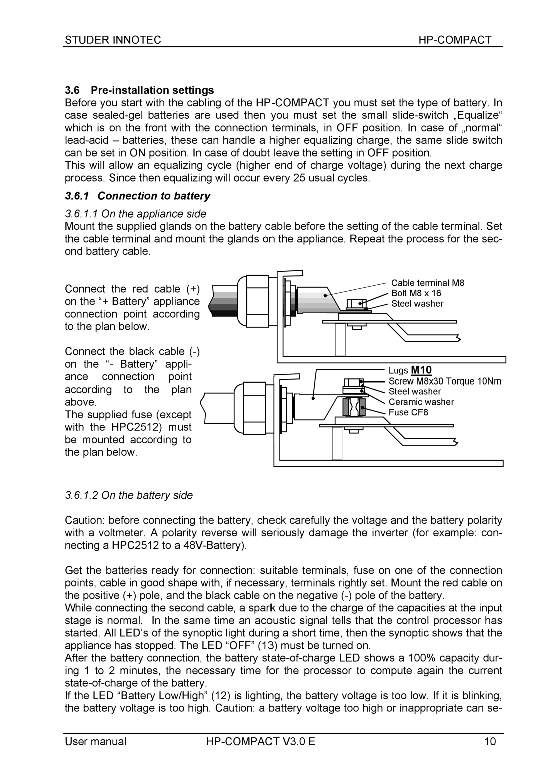
Mount the supplied glands on the battery cable before the setting of the cable terminal. Set the cable terminal and mount the glands on the appliance. Repeat the process for the sec- ond battery cable.
Connect the red cable (+) on the “+ Battery” appliance connection point according to the plan below.
Connect the black cable
The supplied fuse (except with the HPC2512) must be mounted according to the plan below.
Cable terminal M8
Bolt M8 x 16
![]() Steel washer
Steel washer
Lugs M10
Screw M8x30 Torque 10Nm |
Steel washer |
Ceramic washer |
Fuse CF8 |
3.6.1.2 On the battery side
Caution: before connecting the battery, check carefully the voltage and the battery polarity
with a voltmeter. A polarity reverse will seriously damage the inverter (for example: con- necting a HPC2512 to a
Get the batteries ready for connection: suitable terminals, fuse on one of the connection points, cable in good shape with, if necessary, terminals rightly set. Mount the red cable on the positive (+) pole, and the black cable on the negative
While connecting the second cable, a spark due to the charge of the capacities at the input stage is normal. In the same time an acoustic signal tells that the control processor has started. All LED’s of the synoptic light during a short time, then the synoptic shows that the appliance has stopped. The LED “OFF” (13) must be turned on.
After the battery connection, the battery
If the LED “Battery Low/High” (12) is lighting, the battery voltage is too low. If it is blinking, the battery voltage is too high. Caution: a battery voltage too high or inappropriate can se-
User manual | 10 |
