STUDER InnotecXtender
11 Comments of annexes’ figures
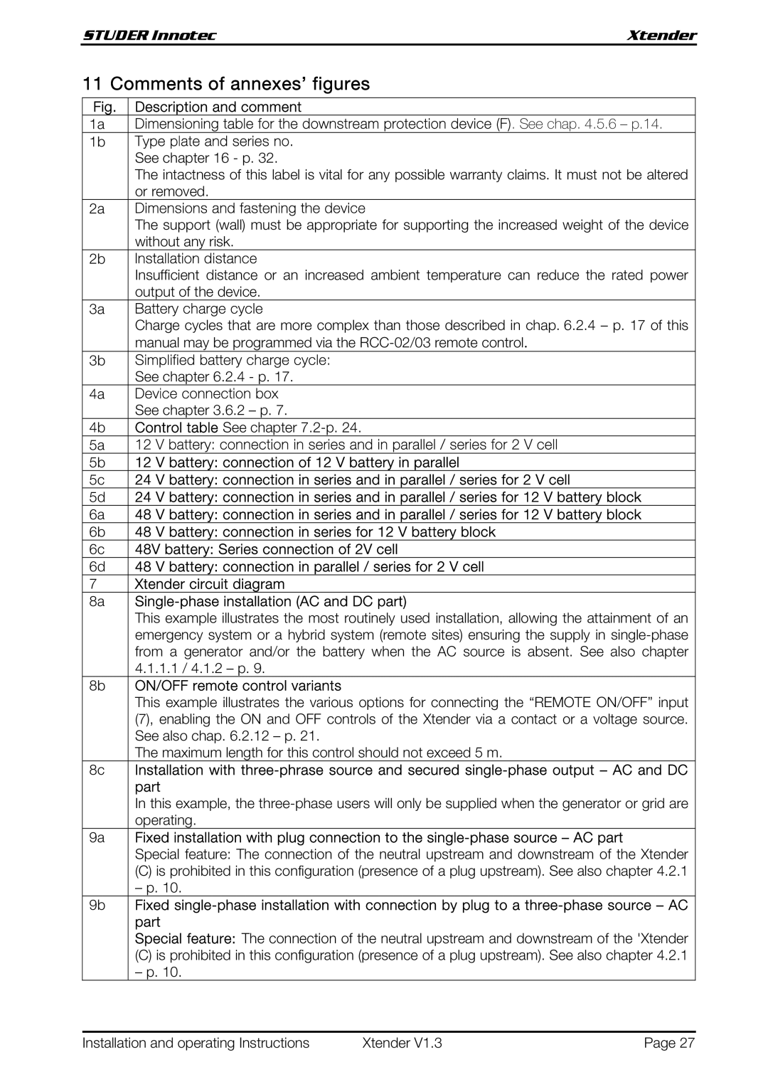
Fig. | Description and comment |
1a | Dimensioning table for the downstream protection device (F). See chap. 4.5.6 – p.14. |
1b | Type plate and series no. |
| See chapter 16 - p. 32. |
| The intactness of this label is vital for any possible warranty claims. It must not be altered |
| or removed. |
2a | Dimensions and fastening the device |
| The support (wall) must be appropriate for supporting the increased weight of the device |
| without any risk. |
2b | Installation distance |
| Insufficient distance or an increased ambient temperature can reduce the rated power |
| output of the device. |
3a | Battery charge cycle |
| Charge cycles that are more complex than those described in chap. 6.2.4 – p. 17 of this |
| manual may be programmed via the |
3b | Simplified battery charge cycle: |
| See chapter 6.2.4 - p. 17. |
4a | Device connection box |
| See chapter 3.6.2 – p. 7. |
4b | Control table See chapter |
5a | 12 V battery: connection in series and in parallel / series for 2 V cell |
5b | 12 V battery: connection of 12 V battery in parallel |
5c | 24 V battery: connection in series and in parallel / series for 2 V cell |
5d | 24 V battery: connection in series and in parallel / series for 12 V battery block |
6a | 48 V battery: connection in series and in parallel / series for 12 V battery block |
6b | 48 V battery: connection in series for 12 V battery block |
6c | 48V battery: Series connection of 2V cell |
6d | 48 V battery: connection in parallel / series for 2 V cell |
7 | Xtender circuit diagram |
8a |
|
| This example illustrates the most routinely used installation, allowing the attainment of an |
| emergency system or a hybrid system (remote sites) ensuring the supply in |
| from a generator and/or the battery when the AC source is absent. See also chapter |
| 4.1.1.1 / 4.1.2 – p. 9. |
8b | ON/OFF remote control variants |
| This example illustrates the various options for connecting the “REMOTE ON/OFF” input |
| (7), enabling the ON and OFF controls of the Xtender via a contact or a voltage source. |
| See also chap. 6.2.12 – p. 21. |
| The maximum length for this control should not exceed 5 m. |
8c | Installation with |
| part |
| In this example, the |
| operating. |
9a | Fixed installation with plug connection to the |
| Special feature: The connection of the neutral upstream and downstream of the Xtender |
| (C) is prohibited in this configuration (presence of a plug upstream). See also chapter 4.2.1 |
| – p. 10. |
9b | Fixed |
| part |
| Special feature: The connection of the neutral upstream and downstream of the 'Xtender |
| (C) is prohibited in this configuration (presence of a plug upstream). See also chapter 4.2.1 |
| – p. 10. |
Installation and operating Instructions | Xtender V1.3 | Page 27 |