| Chapter 5: Advanced Serverboard Setup | ||
|
| ||
|
| ||
|
| ||
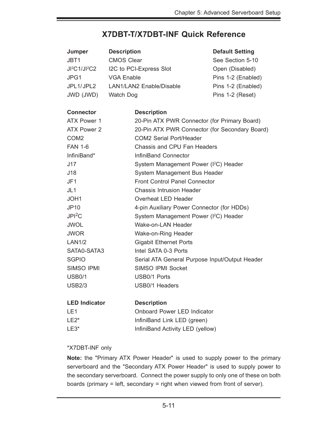
Jumper | Description | Default Setting | |
JBT1 | CMOS Clear | See Section | |
JI2C1/JI2C2 | I2C to | Open (Disabled) | |
JPG1 | VGA Enable | Pins | (Enabled) |
JPL1/ JPL2 | LAN1/LAN2 Enable/Disable | Pins | (Enabled) |
JWD (JWD) | Watch Dog | Pins | (Reset) |
Connector | Description |
ATX Power 1 | |
ATX Power 2 | |
COM2 | COM2 Serial Port/Header |
FAN | Chassis and CPU Fan Headers |
Infi niBand* | Infi niBand Connector |
J17 | System Management Power (I2C) Header |
J18 | System Management Bus Header |
JF1 | Front Control Panel Connector |
JL1 | Chassis Intrusion Header |
JOH1 | Overheat LED Header |
JP10 | |
JPI2C | System Management Power (I2C) Header |
JWOL | |
JWOR | |
LAN1/2 | Gigabit Ethernet Ports |
Intel SATA | |
SGPIO | Serial ATA General Purpose Input/Output Header |
SIMSO IPMI | SIMSO IPMI Socket |
USB0/1 | USB0/1 Ports |
USB2/3 | USB0/1 Headers |
LED Indicator | Description |
LE1 | Onboard Power LED Indicator |
LE2* | Infi niBand Link LED (green) |
LE3* | Infi niBand Activity LED (yellow) |
Note: the "Primary ATX Power Header" is used to supply power to the primary serverboard and the "Secondary ATX Power Header" is used to supply power to the secondary serverboard. Connect the power supply to only one of these on both boards (primary = left, secondary = right when viewed from front of server).