SUPERSERVER
5-9 Connector
Definitions
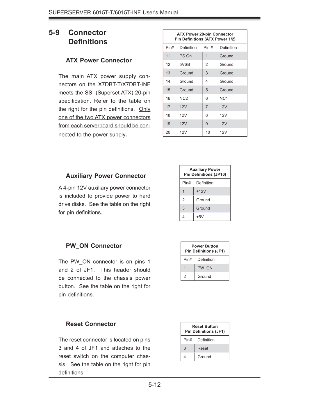
ATX Power Connector
The main ATX power supply con- nectors on the
Auxiliary Power Connector
A
ATX Power
Pin Definitions (ATX Power 1/2)
Pin# | Defi nition | Pin # | Defi nition | |
11 | PS On | 1 | Ground | |
12 | 5VSB |
| Ground | |
2 | ||||
13 | Ground |
| Ground | |
3 | ||||
14 | Ground |
| Ground | |
4 | ||||
15 | Ground |
| Ground | |
5 | ||||
16 | NC2 |
| NC1 | |
6 | ||||
17 | 12V |
| 12V | |
7 | ||||
18 | 12V |
| 12V | |
8 | ||||
19 | 12V | 9 | 12V | |
20 | 12V | 10 | 12V | |
|
|
|
|
Auxiliary Power
Pin Definitions (JP10)
Pin# Defi nition
1+12V
2Ground
3Ground
4+5V
PW_ON Connector
The PW_ON connector is on pins 1 and 2 of JF1. This header should be connected to the chassis power button. See the table on the right for pin defi nitions.
Reset Connector
The reset connector is located on pins 3 and 4 of JF1 and attaches to the reset switch on the computer chas- sis. See the table on the right for pin defi nitions.
Power Button
Pin Definitions (JF1)
Pin# Defi nition
1PW_ON
2 Ground
Reset Button
Pin Definitions (JF1)
Pin# Defi nition
3Reset
4 Ground