SUPERSERVER
Connecting the Control Panel
JF1 contains header pins for various front control panel connectors. See Figure
Figure 5-1. Control Panel Header Pins
20 | 19 |
Ground | NMI |
x (Key) | x (Key) |
Power On LED | Vcc 5V Stby |
IDE/SATA LED | Vcc 3V |
NIC1 LED | Vcc 3V Stby |
NIC2 LED | Vcc 3V Stby |
OH/Fan Fail LED | Vcc 3V |
Reserved | Reserved |
Ground | Reset (Button) |
Ground | Power (Button) |
2 | 1 |
5-4 I/O Ports
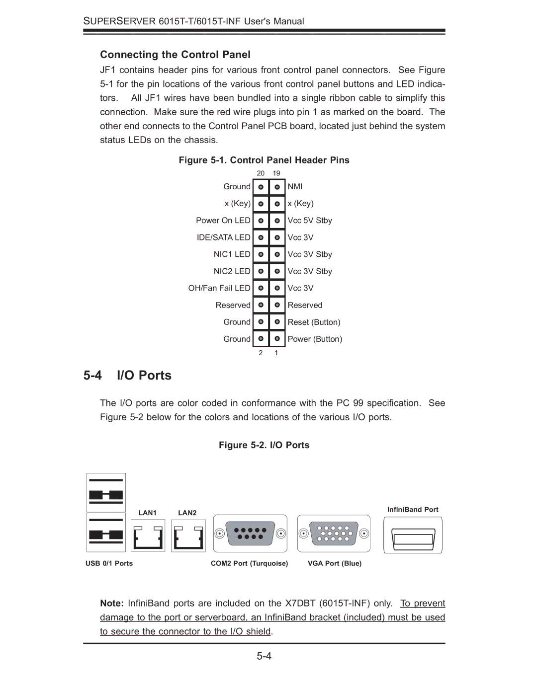
The I/O ports are color coded in conformance with the PC 99 specifi cation. See Figure
Figure 5-2. I/O Ports
| LAN1 |
| LAN2 |
|
| InfiniBand Port | |||||||
|
|
|
|
| |||||||||
|
|
|
|
|
|
|
|
|
|
|
|
|
|
|
|
|
|
|
|
|
|
|
|
|
|
|
|
|
|
|
|
|
|
|
|
|
|
|
|
|
|
|
|
|
|
|
|
|
|
|
|
|
|
|
|
|
|
|
|
|
|
|
|
|
|
|
|
|
|
USB 0/1 Ports | COM2 Port (Turquoise) | VGA Port (Blue) |
Note: Infi niBand ports are included on the X7DBT