2-7 Connector Definitions
Power Connectors
A
Warning: To prevent damage to the power supply or motherboard, please use a power supply that contains a
PW_ON Connector
The PW_ON connector is on pins 15 and 16 of JF1. This header should be connected to the chassis power button. See the table on the right for pin definitions.
HDD/FP UID Switch
The HDD/UID Switch connections are located on pins 13/14 of JF1. Attach a
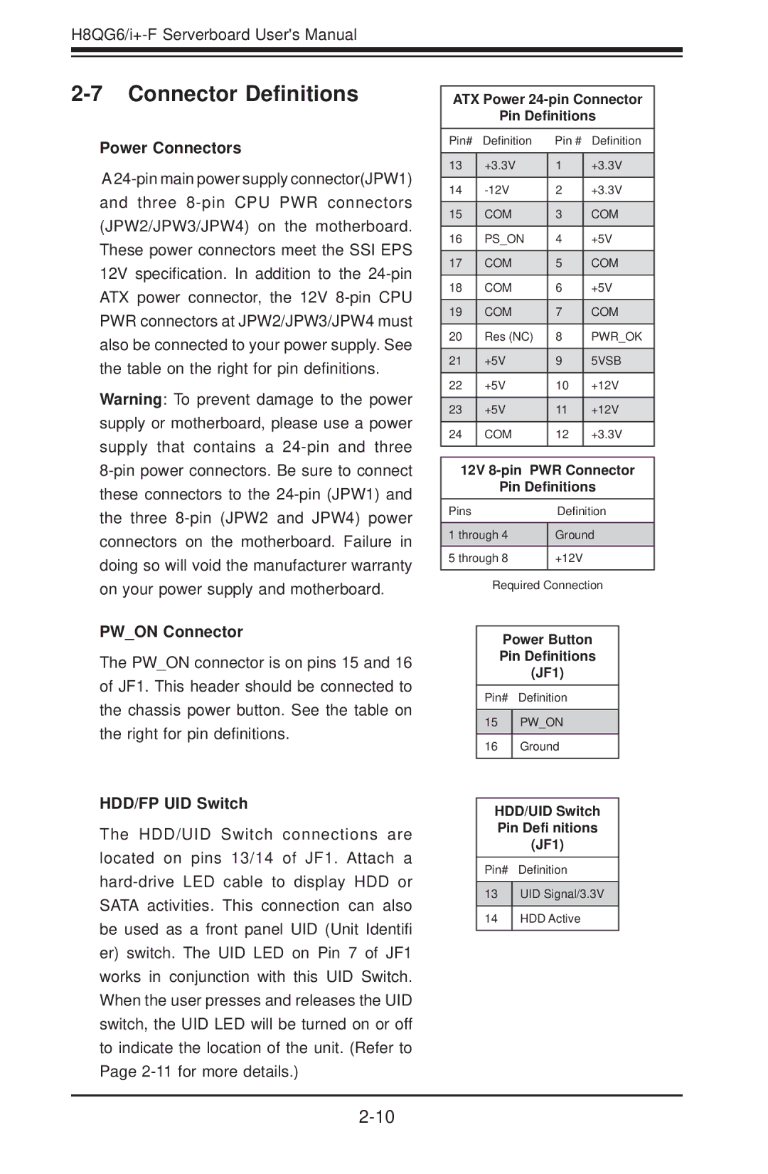
ATX Power
Pin Definitions
Pin# | Definition | Pin # | Definition |
|
|
|
|
13 | +3.3V | 1 | +3.3V |
|
|
|
|
14 | 2 | +3.3V | |
|
|
|
|
15 | COM | 3 | COM |
|
|
|
|
16 | PS_ON | 4 | +5V |
|
|
|
|
17 | COM | 5 | COM |
|
|
|
|
18 | COM | 6 | +5V |
|
|
|
|
19 | COM | 7 | COM |
|
|
|
|
20 | Res (NC) | 8 | PWR_OK |
|
|
|
|
21 | +5V | 9 | 5VSB |
|
|
|
|
22 | +5V | 10 | +12V |
|
|
|
|
23 | +5V | 11 | +12V |
|
|
|
|
24 | COM | 12 | +3.3V |
|
|
|
|
12V | |
Pin Definitions | |
Pins | Definition |
|
|
1 through 4 | Ground |
|
|
5 through 8 | +12V |
|
|
Required Connection
Power Button
Pin Definitions
(JF1)
Pin# Definition
15PW_ON
16Ground
HDD/UID Switch Pin Defi nitions (JF1)
Pin# Definition
13UID Signal/3.3V
14HDD Active