Chapter 2: Installation
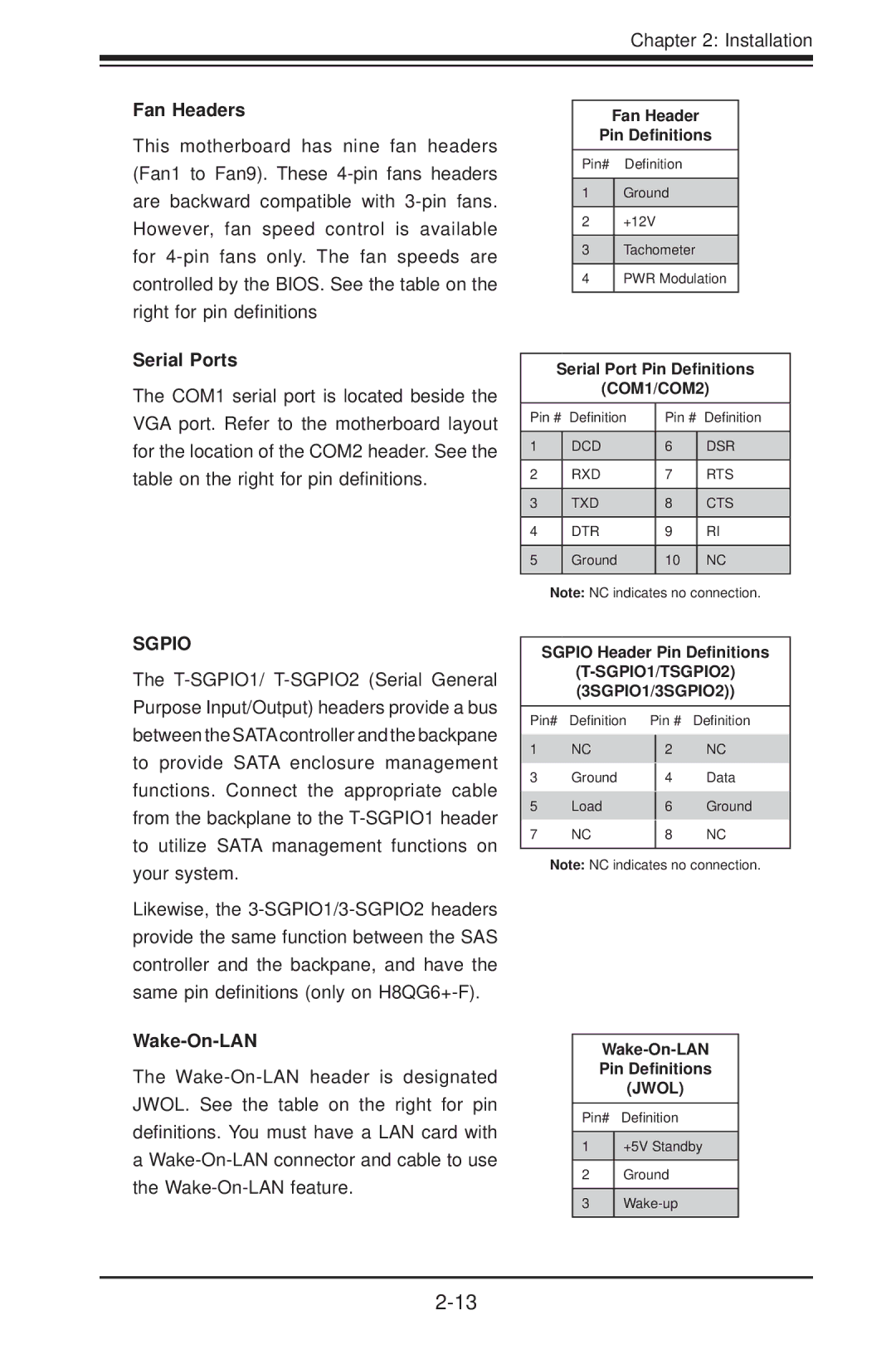
Fan Headers
This motherboard has nine fan headers (Fan1 to Fan9). These
Serial Ports
The COM1 serial port is located beside the VGA port. Refer to the motherboard layout for the location of the COM2 header. See the table on the right for pin definitions.
Fan Header
Pin Definitions
Pin# Definition
1Ground
2+12V
3Tachometer
4PWR Modulation
Serial Port Pin Definitions
(COM1/COM2)
Pin # | Definition | Pin # | Definition |
|
|
|
|
1 | DCD | 6 | DSR |
|
|
|
|
2 | RXD | 7 | RTS |
|
|
|
|
3 | TXD | 8 | CTS |
|
|
|
|
4 | DTR | 9 | RI |
|
|
|
|
5 | Ground | 10 | NC |
|
|
|
|
Note: NC indicates no connection.
SGPIO
The
Likewise, the
Wake-On-LAN
The
a
SGPIO Header Pin Definitions
Pin# | Definition | Pin # | Definition | |
1 | NC |
| NC | |
| 2 | |||
3 | Ground |
|
| Data |
| 4 | |||
5 | Load |
|
| Ground |
| 6 | |||
7 | NC |
|
| NC |
| 8 | |||
|
|
|
|
|
Note: NC indicates no connection.
Pin Definitions
(JWOL)
Pin# Definition
1+5V Standby
2Ground
3
