Power LED/Keylock/Speaker
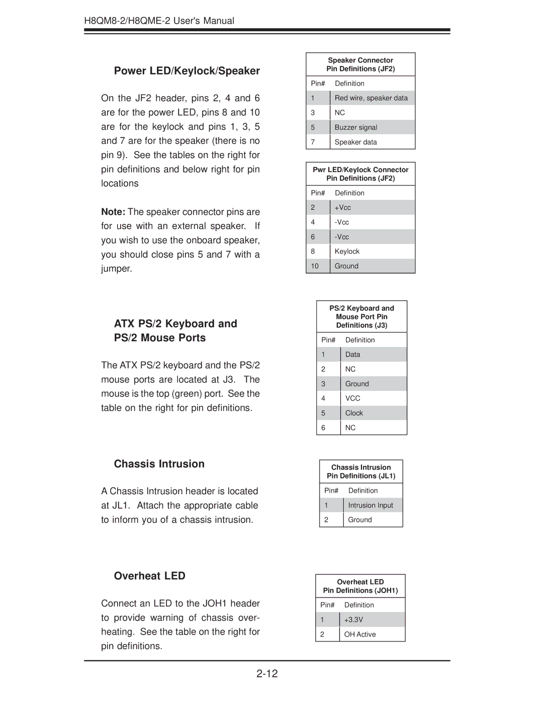
On the JF2 header, pins 2, 4 and 6 are for the power LED, pins 8 and 10 are for the keylock and pins 1, 3, 5 and 7 are for the speaker (there is no pin 9). See the tables on the right for pin definitions and below right for pin locations
Note: The speaker connector pins are for use with an external speaker. If you wish to use the onboard speaker, you should close pins 5 and 7 with a jumper.
ATX PS/2 Keyboard and PS/2 Mouse Ports
The ATX PS/2 keyboard and the PS/2 mouse ports are located at J3. The mouse is the top (green) port. See the table on the right for pin definitions.
Chassis Intrusion
A Chassis Intrusion header is located at JL1. Attach the appropriate cable to inform you of a chassis intrusion.
Overheat LED
Connect an LED to the JOH1 header to provide warning of chassis over- heating. See the table on the right for pin definitions.
Speaker Connector
Pin Definitions (JF2)
Pin# Definition
1 Red wire, speaker data
3 NC
5Buzzer signal
7Speaker data
Pwr LED/Keylock Connector
Pin Definitions (JF2)
Pin# |
| Definition |
2 |
| +Vcc |
| ||
4 |
| |
| ||
6 |
| |
| ||
8 |
| Keylock |
| ||
10 |
| Ground |
| ||
|
|
|
PS/2 Keyboard and
Mouse Port Pin
Definitions (J3)
Pin# Definition
1Data
2NC
3Ground
4VCC
5Clock
6NC
Chassis Intrusion
Pin Definitions (JL1)
Pin# Definition
1Intrusion Input
2Ground
Overheat LED
Pin Definitions (JOH1)
Pin# Definition
1+3.3V
2OH Active