SUPER MICRO Computer X9SVL-IIF, X9SCM-IIF Sata Connections, Sata Connectors Pin Definitions

Models: X9SVL-IIF X9SCM-IIF

1 109
Download 109 pages 37.11 Kb
Page 67
Image 67

Chapter 2: Installation

2-10 SATA Connections

Note the following conditions when connecting the Serial ATA disk drive cables:

Be sure to use the correct cable for each connector. Refer to Page 1-1 for cables that came with your shipment.

A red mark on a wire indicates the location of pin 1.
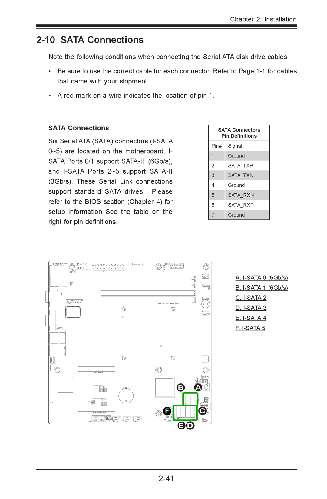
SATA Connections

Six Serial ATA (SATA) connectors (I-SATA 0~5) are located on the motherboard. I- SATA Ports 0/1 support SATA-III (6Gb/s), and I-SATA Ports 2~5 support SATA-II (3Gb/s). These Serial Link connections support standard SATA drives. Please refer to the BIOS section (Chapter 4) for setup information See the table on the right for pin definitions.

SATA Connectors

Pin Definitions

Pin# Signal

1Ground

2SATA_TXP

3SATA_TXN

4Ground

5SATA_RXN

6SATA_RXP

7Ground

KB/MOUSE

JF1

USB/0/1

_LAN


DIMM1BDIMM2B


IPMI


COM1


DIMM2A


DIMM1A


DDR3 1066/1333 UDIMM required


VGA


CPU


LAN1


LAN2


SLOT7 PCI-E 2.0 X8


SLOT6 PCI-E 2.0 X8


B

A


SLOT5 PCI-E 2.0 X4 ON X8


I-SATA1 I-SATA0


F


C


JBT1


SLOT4 PCI-E 2.0 X4 ON X8


I-SATA5

I-SATA4

I-SATA3 I-SATA2


COM2

USB 12/13

USB4/5

USB2/3

USB11


D


E

A.I-SATA 0 (6Gb/s)

B.I-SATA 1 (6Gb/s)

C.I-SATA 2

D.I-SATA 3

E.I-SATA 4

F.I-SATA 5

2-41

Page 67
Image 67
SUPER MICRO Computer X9SVL-IIF, X9SCM-IIF user manual Sata Connections, Sata Connectors Pin Definitions