![]()
![]()
![]()
![]()
![]()
![]() X9SCM-IIF/X9SCL-IIF
X9SCM-IIF/X9SCL-IIF
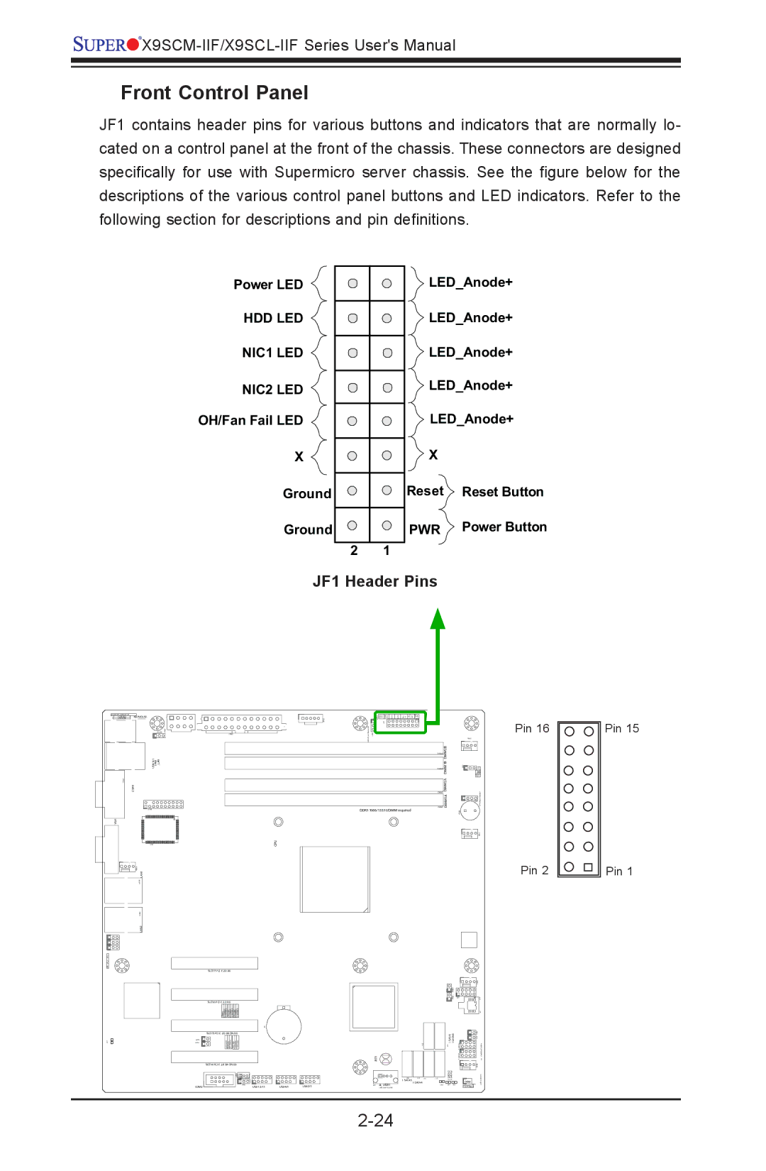
Front Control Panel
JF1 contains header pins for various buttons and indicators that are normally lo- cated on a control panel at the front of the chassis. These connectors are designed specifically for use with Supermicro server chassis. See the figure below for the descriptions of the various control panel buttons and LED indicators. Refer to the following section for descriptions and pin definitions.
Power LED ![]()
HDD LED NIC1 LED ![]() NIC2 LED
NIC2 LED ![]()
OH/Fan Fail LED
X
Ground
Ground
2 1
LED_Anode+
LED_Anode+
LED_Anode+
LED_Anode+
LED_Anode+
X |
|
Reset | Reset Button |
PWR | Power Button |
JF1 Header Pins
KB/MOUSE |
| JF1 |
USB/0/1 | IPMI | LAN |
COM1
DDR3 1066/1333 UDIMM required
VGA
CPU
LAN2LAN1
SLOT7
SLOT6
SLOT5
|
|
|
| JBT1 |
|
| SLOT4 |
|
|
|
|
|
|
|
| ||
COM2 | USB 12/13 | USB4/5 | USB2/3 | USB11 |
|
Pin 16
DIMM1A DIMM2A DIMM1B DIMM2B
Pin 2
Pin 15
Pin 1