![]()
![]()
![]()
![]()
![]()
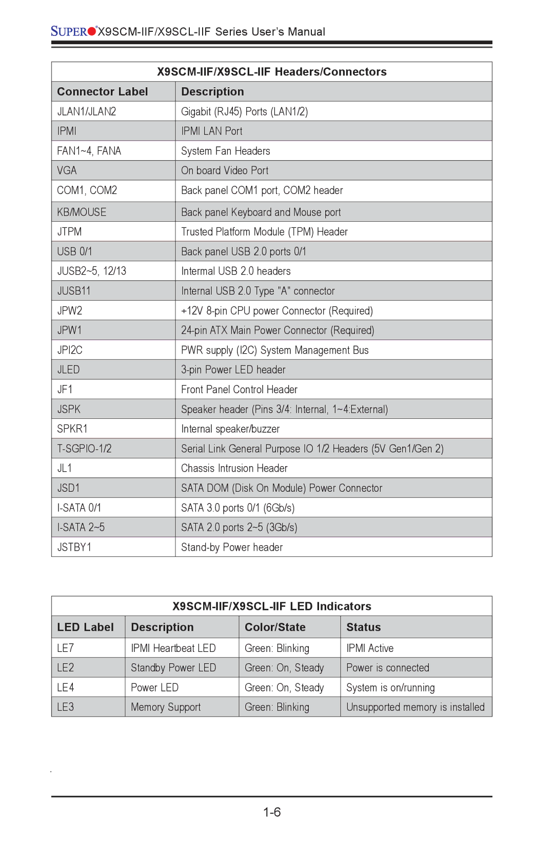
![]() X9SCM-IIF/X9SCL-IIF
X9SCM-IIF/X9SCL-IIF
|
| |
Connector Label |
| Description |
JLAN1/JLAN2 |
| Gigabit (RJ45) Ports (LAN1/2) |
|
|
|
IPMI |
| IPMI LAN Port |
|
|
|
FAN1~4, FANA |
| System Fan Headers |
|
|
|
VGA |
| On board Video Port |
|
|
|
COM1, COM2 |
| Back panel COM1 port, COM2 header |
|
|
|
KB/MOUSE |
| Back panel Keyboard and Mouse port |
|
|
|
JTPM |
| Trusted Platform Module (TPM) Header |
|
|
|
USB 0/1 |
| Back panel USB 2.0 ports 0/1 |
|
|
|
JUSB2~5, 12/13 |
| Intermal USB 2.0 headers |
|
|
|
JUSB11 |
| Internal USB 2.0 Type "A" connector |
|
|
|
JPW2 |
| +12V |
|
|
|
JPW1 |
| |
|
|
|
JPI2C |
| PWR supply (I2C) System Management Bus |
|
|
|
JLED |
| |
|
|
|
JF1 |
| Front Panel Control Header |
|
|
|
JSPK |
| Speaker header (Pins 3/4: Internal, 1~4:External) |
|
|
|
SPKR1 |
| Internal speaker/buzzer |
|
|
|
| Serial Link General Purpose IO 1/2 Headers (5V Gen1/Gen 2) | |
|
|
|
JL1 |
| Chassis Intrusion Header |
|
|
|
JSD1 |
| SATA DOM (Disk On Module) Power Connector |
|
|
|
| SATA 3.0 ports 0/1 (6Gb/s) | |
|
|
|
| SATA 2.0 ports 2~5 (3Gb/s) | |
|
|
|
JSTBY1 |
| |
|
|
|
LED Label | Description | Color/State | Status |
|
|
|
|
LE7 | IPMI Heartbeat LED | Green: Blinking | IPMI Active |
|
|
|
|
LE2 | Standby Power LED | Green: On, Steady | Power is connected |
|
|
|
|
LE4 | Power LED | Green: On, Steady | System is on/running |
LE3 | Memory Support | Green: Blinking | Unsupported memory is installed |
|
|
|
|