Inverter/Charger Installation
AUX-RPO: User Remote Power Off (RPO)
Connecting
The external switch if pressed overrides the control provided from the front panel.
If the external switch is cleared (not pressed), the system can be enabled back from the front panel.
Select an external switch with normal open contact; consult your local system designer or qualified technician for specific installation instructions.
User Line Wiring
Use twisted pairs of #24 AWG to #12 AWG for connections. Carefully route the wires away from high power load cables to minimize noise effects on signal integrity.
AUX Port Terminal Assignments
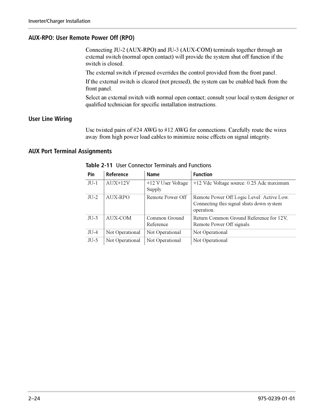
Table 2-11 User Connector Terminals and Functions
Pin | Reference | Name | Function |
|
|
|
|
AUX+12V | +12 V User Voltage | +12 Vdc Voltage source: 0.25 Adc maximum | |
|
| Supply |
|
| Remote Power Off | Remote Power Off Logic Level: Active Low. | |
|
|
| Connecting this signal shuts down system |
|
|
| operation. |
| Common Ground | Return Common Ground Reference for 12V, | |
|
| Reference | Remote Power Off signals. |
Not Operational | Not Operational | Not Operational | |
Not Operational | Not Operational | Not Operational | |
|
|
|
|
