Step 5: Installing Additional Inverters
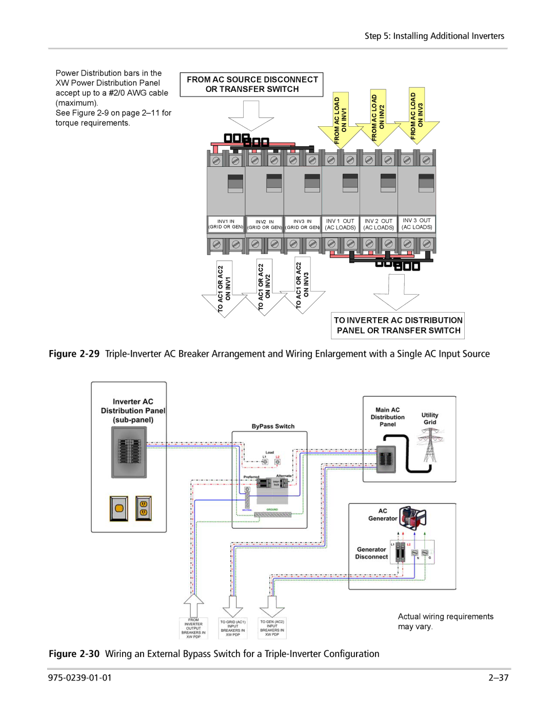
Power Distribution bars in the XW Power Distribution Panel accept up to a #2/0 AWG cable (maximum).
See Figure
FROM AC SOURCE DISCONNECT
OR TRANSFER SWITCH
|
|
|
|
|
|
|
|
|
|
|
|
|
|
|
|
|
|
|
|
|
|
|
|
|
|
|
|
|
|
|
|
|
|
|
|
|
|
|
|
|
|
|
|
|
|
|
|
|
|
|
|
|
|
|
|
|
|
|
|
|
|
|
|
|
|
|
|
|
|
|
|
|
|
|
|
|
|
|
|
|
|
|
|
|
|
|
|
|
|
|
|
|
|
|
|
|
|
|
|
|
|
|
|
|
|
|
|
|
|
|
|
|
|
|
|
|
|
|
|
|
|
|
|
|
|
|
|
|
|
|
|
|
|
|
|
|
|
|
|
|
|
|
|
|
|
|
|
|
|
|
|
|
|
|
|
| INV1 | IN | INV2 | IN |
| INV3 | IN | ||||
(GRID OR GEN) | (GRID OR GEN) | (GRID OR GEN) | |||||||||||
|
|
|
|
|
|
|
|
|
|
|
|
|
|
|
|
|
|
|
|
|
|
|
|
|
|
|
|
|
|
|
|
|
|
|
|
|
|
|
|
|
|
|
|
|
|
|
|
|
|
|
|
|
|
|
|
FROM AC LOAD ON INV1 | FROM AC LOAD ON INV2 | FROM AC LOAD ON INV3 |
INV 1 OUT | INV 2 OUT | INV 3 OUT |
(AC LOADS) | (AC LOADS) | (AC LOADS) |
TO AC1 OR AC2 ON INV1 | TO AC1 OR AC2 ON INV2 | TO AC1 OR AC2 ON INV3 |
TO INVERTER AC DISTRIBUTION
PANEL OR TRANSFER SWITCH
Figure 2-29 Triple-Inverter AC Breaker Arrangement and Wiring Enlargement with a Single AC Input Source
Actual wiring requirements may vary.