Xantrex Technology XW4024-120/240-60, XW4548-120/240-60, XW6048-120/240-60 manual

Models: XW4024-120/240-60, XW4548-120/240-60, XW6048-120/240-60

1 136
Download 136 pages 52.84 Kb
Page 56
Image 56

Inverter/Charger Installation

AC Wiring for a Dual-Inverter System

1.Disconnect the AC wires (from the utility grid or generator and to the sub-panel) and remove the factory-installed distribution bars connected to top and bottom terminals on the AC breakers.

2.Remove bypass interlock bracket.

3.Disconnect INV1 AC LOAD (INV1 L1-LOAD, INV1 L2-LOAD) wires from top terminals on right-hand side breaker.

4.Add three additional dual-pole AC breakers (supplied in 865-1020) next to the existing three dual-pole AC breakers.

5.Attach the four distribution bars (supplied in 865-1020) to top and bottom of AC breakers as shown in dual-inverter system wiring diagrams.

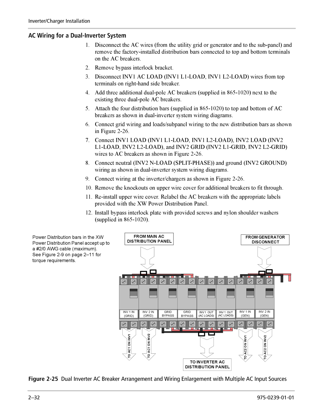
6.Connect grid wiring and loads/subpanel wiring to the new distribution bars as shown in Figure 2-26.

7.Connect INV1 LOAD (INV1 L1-LOAD, INV1 L2-LOAD), INV2 LOAD (INV2 L1-LOAD, INV2 L2-LOAD), and INV2 GRID (INV2 L1-GRID, INV2 L2-GRID) wires to AC breakers as shown in Figure 2-26.

8.Connect neutral (INV2 N-LOAD (SPLIT-PHASE)) and ground (INV2 GROUND) wiring as shown in dual-inverter system wiring diagrams.

9.Connect wiring at the inverter/chargers as shown in Figure 2-26.

10.Remove the knockouts on upper wire cover for additional breakers to fit through.

11.Re-install upper wire cover. Relabel the AC breakers with the appropriate labels provided with the XW Power Distribution Panel.

12.Install bypass interlock plate with provided screws and nylon shoulder washers (supplied in 865-1020).

Power Distribution bars in the XW Power Distribution Panel accept up to a #2/0 AWG cable (maximum).

See Figure 2-9 on page 2–11 for torque requirements.

FROM MAIN AC

DISTRIBUTION PANEL

FROM GENERATOR

DISCONNECT

INV 1 IN

INV 2 IN

(GRID)

(GRID)

GRID

GRID

BYPASS

BYPASS

INV 1 OUT

INV 1 OUT

(AC LOADS)

(AC LOADS)

INV 1 IN

INV 2 IN

(GEN)

(GEN)

TO AC1 ON INV1

TO AC1 ON INV2

TO AC2 ON INV1

TO AC2 ON INV2

TO INVERTER AC

DISTRIBUTION PANEL

Figure 2-25Dual Inverter AC Breaker Arrangement and Wiring Enlargement with Multiple AC Input Sources

2–32

975-0239-01-01

Page 56
Image 56
Xantrex Technology XW4024-120/240-60, XW4548-120/240-60, XW6048-120/240-60 manual AC Wiring for a Dual-Inverter System