Xantrex Technology XW4024-120/240-60, XW4548-120/240-60, XW6048-120/240-60 Clearance Requirements

Models: XW4024-120/240-60, XW4548-120/240-60, XW6048-120/240-60

1 136
Download 136 pages 52.84 Kb
Page 27
Image 27

Pre-Installation

Clearance Requirements

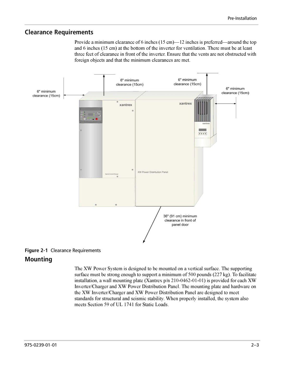
Provide a minimum clearance of 6 inches (15 cm)—12 inches is preferred—around the top and 6 inches (15 cm) at the bottom of the inverter for ventilation. There must be at least three feet of clearance in front of the inverter. Ensure that the vents are not obstructed with foreign objects and that the minimum clearances are met.

Figure 2-1Clearance Requirements

Mounting

The XW Power System is designed to be mounted on a vertical surface. The supporting surface must be strong enough to support a minimum of 500 pounds (227 kg). To facilitate installation, a wall mounting plate (Xantrex p/n 210-0462-01-01) is provided for each XW Inverter/Charger and XW Power Distribution Panel. The mounting plate and hardware on the XW Inverter/Charger and XW Power Distribution Panel are designed to meet standards for structural and seismic stability. When properly installed, the system also meets Section 59 of UL 1741 for Static Loads.

975-0239-01-01

2–3

Page 27
Image 27
Xantrex Technology XW4024-120/240-60, XW4548-120/240-60, XW6048-120/240-60 manual Clearance Requirements, Mounting