![]()
![]()
![]()
![]()
![]()
![]() X9SCM-IIF/X9SCL-IIF
X9SCM-IIF/X9SCL-IIF
T-SGPIO 1/2 Headers
Two
Pin Definitions
Purpose Input/Output) headers are located near the SATA connectors on the motherboard. These headers are used to communicate with the enclosure management chip in the
Pin#
1
3
5
7
Definition
NC
Ground
Load
Clock
Pin Definition
2NC
4 DATA Out
6Ground
8NC
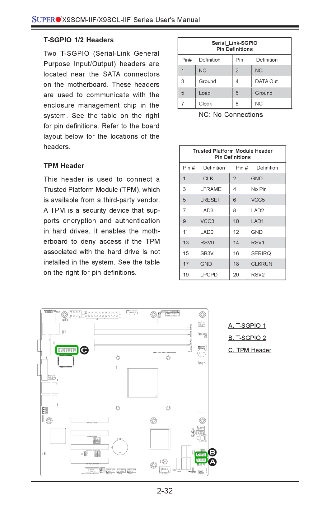
system. See the table on the right for pin definitions. Refer to the board layout below for the locations of the headers.
NC: No Connections
Trusted Platform Module Header
Pin Definitions
TPM Header
This header is used to connect a Trusted Platform Module (TPM), which is available from a
KB/MOUSE | JF1 |
Pin # Definition
1LCLK
3LFRAME
5 | LRESET |
7 | LAD3 |
9VCC3
11LAD0
13RSV0
15SB3V
17GND
19LPCPD
Pin # Definition
2GND
4No Pin
6VCC5
8LAD2
10LAD1
12GND
14RSV1
16SERIRQ
18CLKRUN
20RSV2
USB/0/1 | LAN |
|
|
|
|
|
| IPMI |
|
|
|
|
|
COM1 |
|
|
|
|
|
|
| C |
|
|
| DDR3 1066/1333 UDIMM required |
|
VGA |
|
|
|
|
|
|
|
|
| CPU |
|
|
|
LAN1 |
|
|
|
|
|
|
LAN2 |
|
|
|
|
|
|
| SLOT7 |
|
|
|
|
|
| SLOT6 |
|
|
|
|
|
| SLOT5 |
|
|
|
|
|
|
|
|
|
| JBT1 |
|
| SLOT4 |
|
|
|
|
|
|
|
|
|
| ||
| COM2 | USB 12/13 | USB4/5 | USB2/3 | USB11 |
|
DIMM1A DIMM2A DIMM1B DIMM2B
A.
B.
C. TPM Header
B
A
