|
|
|
| OT |
|
|
|
| IL |
|
|
|
| P |
ILO |
|
|
| |
P | T |
|
| TH |
F |
| O |
| |
F |
| N | W | OL |
O | it | |||
|
|
| ||
|
|
|
| |
|
|
|
| TP |
|
|
| H I | |
|
|
|
| TPTH |
EA
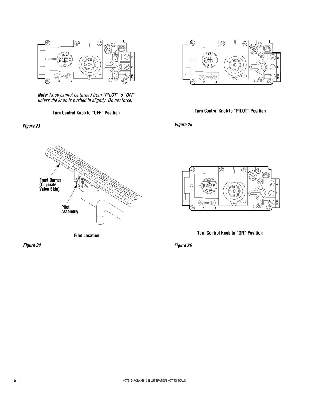
Note: Knob cannot be turned from “PILOT” to “OFF” unless the knob is pushed in slightly. Do not force.
Turn Control Knob to “OFF” Position
Figure 23
Front Burner (Opposite Valve Side)
Pilot
Assembly
Pilot Location
Figure 24
ILOT
P
T | ON | |
it | ||
O | ||
I | W OL | |
L |
| |
P | FFO | |
| ||
| H I |
EA
Turn Control Knob to “PILOT” Position
Figure 25
ILOT
P
N | it |
| O |
|
|
| F | W OL | |
O |
|
| F | |
|
|
|
| |
| T | P |
|
|
| OLI |
|
| |
|
|
|
| H I |
EA
Turn Control Knob to “ON” Position
Figure 26
TPTH TP TH
TPTH TP TH
16
NOTE: DIAGRAMS & ILLUSTRATION NOT TO SCALE.
