OFF/ON Blower
Wall Switch
| To Fuse or |
Black | Circuit Breaker |
| |
Receptacle | 120V |
White | }60HzAC |
Fireplace |
|
Junction Box |
|
Blower Wiring Diagram
Ground Wire
Connection
White |
|
|
(Supply) |
| Blower |
|
| |
|
| (Lower) |
|
| Outlet |
120 Vac |
|
|
60 Hz | Bipolar |
|
|
| |
| Terminal |
|
Black | Screw | Black |
(Supply) |
| Wire |
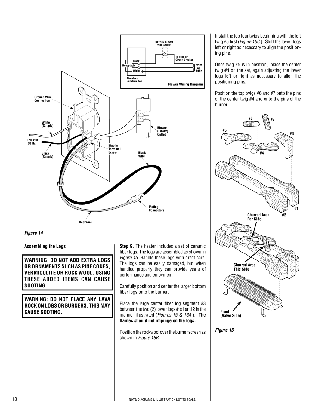
Install the top four twigs beginning with the left twig #5 first (Figure 16C ). Shift the lower logs left or right as necessary to align the position- ing pins.
Once twig #5 is in position, place the center twig #4 on the set, again adjusting the lower logs left or right as necessary to align the positioning pins.
Position the top twigs #6 and #7 onto the pins of the center twig #4 and onto the pins of the burner.
#6 #7
#5
#3
#4
Red Wire
Figure 14
Assembling the Logs
WARNING: DO NOT ADD EXTRA LOGS OR ORNAMENTS SUCH AS PINE CONES, VERMICULITE OR ROCK WOOL. USING THESE ADDED ITEMS CAN CAUSE SOOTING.
WARNING: DO NOT PLACE ANY LAVA ROCK ON LOGS OR BURNERS. THIS MAY CAUSE SOOTING.
![]() Mating
Mating
Connectors
Step 9. The heater includes a set of ceramic fiber logs. The logs are assembled as shown in Figure 15. Handle these logs with great care. The logs can be easily damaged, but when handled properly they can provide years of performance and enjoyment.
Carefully position and center the larger bottom fiber logs onto the burner.
Place the large center fiber log segment #3 between the two (2) lower logs #'s1 and 2 in the manner illustrated (Figures 15 & 16A ). The
flames should not impinge on the logs.
Position the rockwool over the burner screen as shown in Figure 16B.
#1
Charred Area | #2 |
Far Side |
|
Charred Area
This Side
Front
(Valve Side)
Figure 15
10
NOTE: DIAGRAMS & ILLUSTRATION NOT TO SCALE.
